


ZX-14 Chain Slack Adjustment
The drive chain will need to be tightened periodically, especially when the chain is new. It also will need to be adjusted when replacing the drive chain or switching to different sized sprockets.
The movement of the rear suspension requires that the drive chain have a certain amount of looseness for both to operate properly. The looseness in the chain allows the suspension to operate without stretching or breaking the drive chain or stressing the bearings that the chain wheels turn on. The looseness of the drive chain is called chain slack. When weight is placed on the bike, the suspension compresses which pulls the chain tighter, reducing the chain slack. The reaction of the rear shock and the swing arm to road irregularities reduces chain slack during opperation even further.
The ideal chain slack is that which would allow complete compression of the rear suspension while not attaining 0 slack until that point. The manufacturer has determined the proper amount of chain slack to be a minimum of 1.3 inches as measured with the rear suspension compressed by weight of the bike only. In practice, this amount of slack should allow for a complete bottom-out of the rear suspension without stressing the chain or other parts of the final drive.
Adjust looser, not tighter. A chain that is too loose will be obvious upon inspection before it ever becomes loose enough to fall off the sprockets or cause severe damage. A chain that is too tight could snap. For this reason, I always give preference to adjusting the drive chain looser rather than tighter. If the chain comes off, it will either wrap around the engine sprocket and gouge the bottom of the motor out or wrap around the swing arm causing a rear wheel lockup. A chain that has come off does not usually fly out harmlessly. Proper chain slack is important but it is also simple enough to be one of the maintenance procedures that the manufacturer expects owners to be able to do themselves.
Do not run the engine when measuring or adjusting chain slack or performing any other drive chain procedures. Amputations. Need I say more?? It has happened more times than I can count on both hands!
Measure chain slack on the top and bottom chain runs, then add those two for a final figure. This procedure is described in detail below. It is not how the manufacturer recommends measuring chain slack. They recommend measuring the chain slack on one run but if you have not already discovered, that is impossible because of the swingarm is in the way. You can only measure part of the chain slack on both runs.
Make small adjustments. As amazing as it may seem, turning the adjuster screws one sixth of a turn is often enough to tighten the chain properly. There are adjustment reference marks on the swing arm. You will never need to adjust the blocks one entire mark tighter in a single adjustment or even half a mark tighter. That would be much too tight.
Tools:
rear spool stand
15” steel ruler
straight slot screw driver
pliers
32mm impact socket
24” breaker bar
Two 12mm open end wrenches
rubber mallet
torque wrench
new cotter pin
Measuring Drive Chain Slack
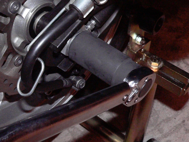
1. It is best to find the point of greatest tension in the drive chain before measuring the slack. Put the bike on a rear spool stand. Rotate the wheel slowly to find the point of greatest tension. Please be very careful not to roll fingers into the sprockets. Feel the chain from outside of the run and roll the wheel the direction that will not pull fingers into the sprocket.
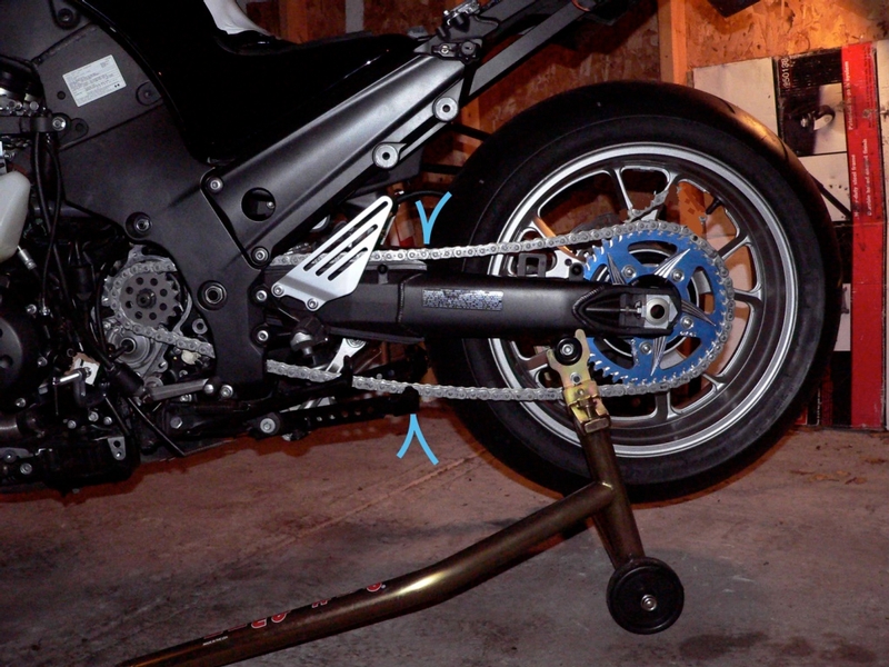
When the point of greatest tension is found the drive chain slack may be properly measured midway between the front and rear sprockets (at the points marked by the blue pointers in the photo above).
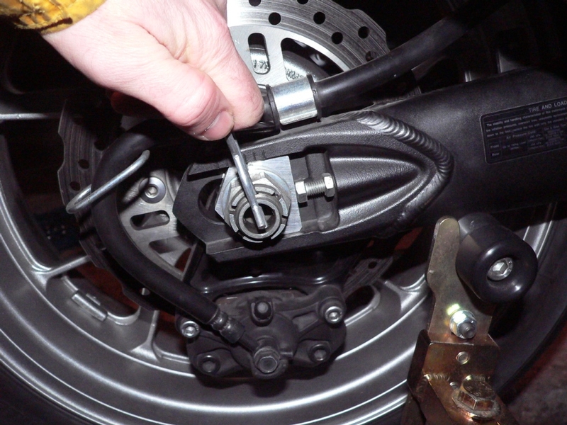
2. Slide a 15” steel ruler inside of the swing arm on the left side. The ruler edge should touch the left front inside corner of the swing arm. To hold the ruler steady, the top of the ruler will rest perfectly inside of the slot in the mud flap behind the passenger foot peg bracket mounts. The back edge of the belly pan happens to also be at an ideal location to rest the bottom edge of the ruler if that is preferable. 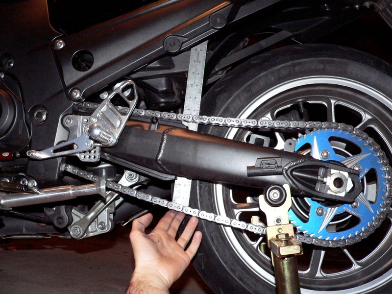
3. Pull the bottom run of the chain down using only approximately 2 lbs of force. Measure the distance of travel in the bottom run. Now measure the top run of the chain in the same way, pulling it upward with approximately 2 pounds of force. Add the measurements together for the total chain slack. Combined measurement should be be 1 and a third to 1 and one half inches. If it is out of spec, it needs to be adjusted.
Drive chain slack: 1.3 inch ~ 1.5 inches.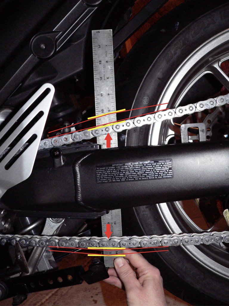
Pull the top chain run up and measure the travel. Pull the bottom chain run down and measure the travel. Add both measurements for total chain slack. Also, note that the ruler is resting on the belly pan bracket which is conveniently located in line with the proper points for measuring chain slack.
Adjust Drive Chain Slack
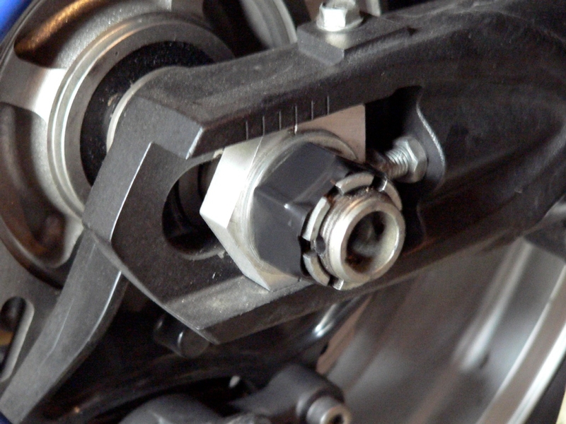
4. Note the position of the adjuster block in relationship to the marks at the top of the swing arm adjuster slot. Normal chain adjustments do not require much movement of the block at all. However, in some situations it is helpful to know where the block was before the adjustment. The marks should always be identical on both the left and the right adjuster to maintain proper axle alignment. 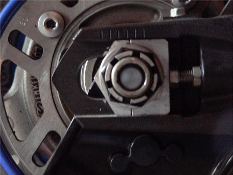
When visually checking adjuster block position, I square up my line of sight by looking straight down the hollow center of the axle.
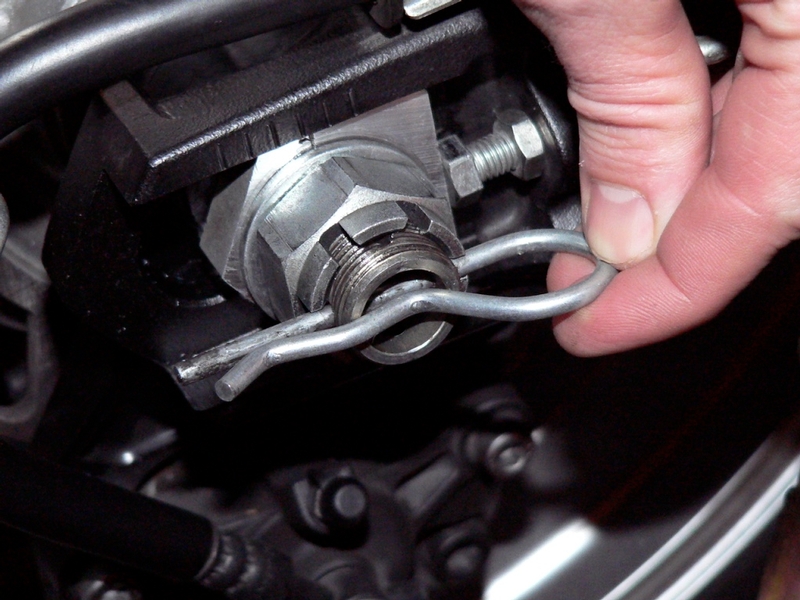
5. Use a straight slot screw driver to straighten the cotter pin ends and pull the pin with a pair of pliers.
I have a reusable retainer pin that I secure the axle nut with. I have also seen a setup using a linchpin where the ring folds securely over the protruding threads of the axle.
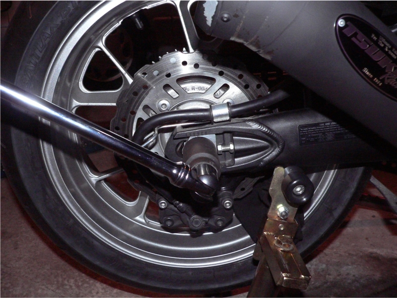
6. Use a 32mm impact socket and a 24” breaker bar to loosen the axle nut. Make the nut loose enough that the washer behind it is free.
I tape my axle nut with electrical tape to help protect it from being marked by the socket when the nut is loosened or torqued.
7. Use a 12mm open end wrench to hold the left adjuster screw steady. Use another 12mm open end wrench to loosen the adjuster screw locknut. Do not move the adjuster screw yet. Repeat the locknut loosening procedure on the right hand adjuster.
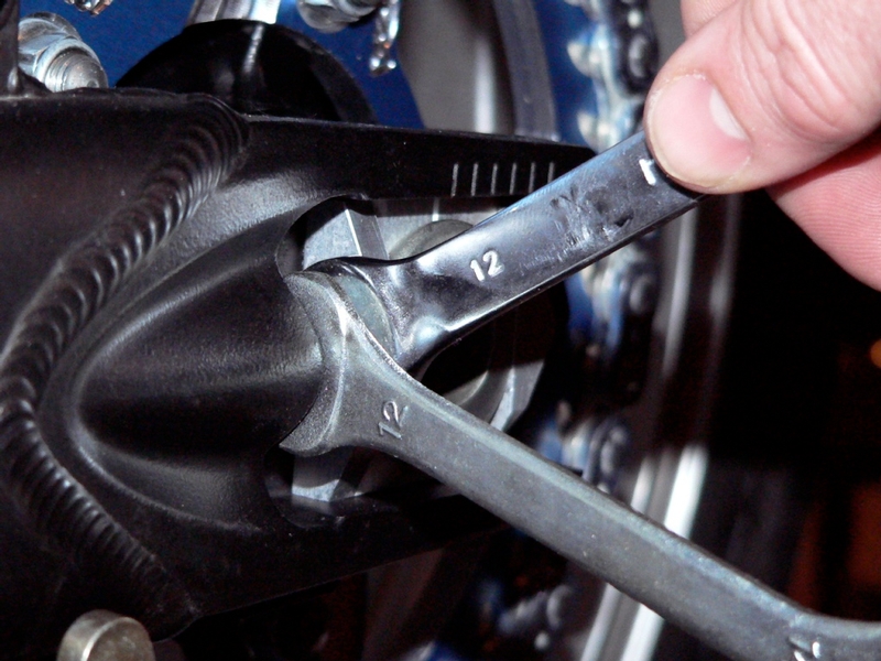
8. Turn the left adjuster only a very small amount at a time, counterclockwise (out) to tighten the chain or clockwise (in) to loosen the chain. One sixth of a turn, (one hex flat) will make approximately a 1/8 inch adjustment in chain slack. Turn the right adjuster the same amount as the left. I sometimes mark the outside flat of the adjuster bolt on each side before I turn it. This provides a reference point to check that both sides have been turned the same amount. It is not normally necessary to mark more than one flat because the adjuster is usually not turned more than 1 flat to adjust the chain.
9. Kick the rear tire forward or use a rubber mallet to bump the rear tire in tight against the adjuster screws. Measure the chain slack as directed in steps 2 and 3 above. Adjust both sides equally if necessary. 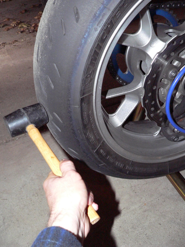
With the axle nut loose, the swing arm forks are not compressed. Expect the chain slack measurement to be approximately 1/8 inch less after the axle nut is tightened and the wheel is pulled back accordingly.
10. When the proper amount of slack is achieved, (remember that it will be 1/8” less after you tighten the axle nut) hold the adjuster screw with a 12mm open end wrench. Tighten the adjuster screw locknut against the front of the adjuster block slot with another 12mm open end wrench. Repeat this process for the adjuster on the other side.
11. Use a 32mm impact socket and torque wrench to tighten the axle nut. Inspect the the adjuster block marks on the swing arm. The adjuster block and marks should look the same on both sides when the rear wheel is properly aligned.
axle nut torque 93.7 ft lbs.
12. Take a final chain slack measurement. The chain slack will be approximately 1/8 inch less than it was before the axle nut was tightened and the swing arm forks compressed, pushing the wheel back slightly. Readjust the chain slack if it is not in spec range of 1.3 inch ~ 1.5 inch.
13. Secure the axle nut with a new cotter pin (or a reusable pin such as that in the photo below). If the axle nut torque did not result in the castle slots lining up with the holes in the axle, tighten the nut to the nearest alignment. Then loosen the nut until the castle slots go back past the hole they were aligned to. Torque once again to 93.7 foot lbs.
The procedure to line up the axle nut castle slots to the holes in the axle worked for me at least one time. I normally just mess around with the nut loosening and retightening, perhaps to a slightly lower torque value, until the nut and the holes in the axle line up.
* Last updated by: Rook on 2/17/2018 @ 9:28 AM *