


HM PLUS Quickshifter Installation
The HM PLUS shifter works by cutting ignition briefly so that the transmission may be shifted smoothly without disengaging the clutch. The throttle needn’t be closed since ignition is cut during the shift. In this way it is possible to maintain wide open throttle or any throttle position throughout the upshifts.
The HM PLUS quickshifter consists of a strain gauge sensor, an LCD module, a loom and the wiring connecting all of these parts. The sensor reacts to pressure on the shift linkage when the shift lever is moved. The loom is the wiring that connects to the stick coils. The LCD module is used to select and display settings of the unit. These three settings are:
Killtime --The number of milliseconds, from 50 to 150, that ignition will be cut in the motor in order to allow for a smooth, clutchless upshift.
Sensititvity --The amount of force on the shift linkage required to be registered by the sensor before an ignition cut is executed. This setting is from 00-100. 50 is approximately average.
Compression or Extension --Compression is selected if it is desired that the sensor react to toe-up upshifts. Extension is selected for toe-down upshifts as in Moto GP shift pattern. Both Compression and Extension can be selected if both toe-up and toe-down shifting is required such as may be the case with some teams of endurance racing.
The HM quickshifter is made by a British company and distributed in the US by a company called Annitori. HM quickshifter kits are made in several versions to accomodate differerent interfacing needs of various motorcycles. The HM PC may be used on the ZX-14 by connecting the HM quickshifter to a Power Commander III or PowerCommander V. The HM PLUS connects directly to the stick coils on the ZX-14 and it is considered to be the best and most up to date choice for motorcycles with plugtop coils. This tutorial details the installation of the HM PLUS shifter. There is a third choice for the ZX-14 called the RL. The RL does not have the LCD module and is is limited to only a few of the most common user settings. The optimum user settings are so uniform across most sport bikes that the RL will almost always work as well as one of the models with the LCD module and at a much reduced price. All HM shifters are designed to be used with after market rearsets with shift rod linkage but stock pegs with diect lever to shift shaft configuration may be adapted.
This tutorial gives specific instructions for installing the HM PLUS shifter with module located under the seat. Much of the information in this tutorial will be helpful for other LCD module locations. At the end of this tutorial, I included the Annitori RL quickshifter Install Sheet to provide general installation information of the strain gauge.
A number of members have reported that the grommet inside the female connectors to the stick coils falls out easily. These gromets are located in both the HM loom female connectors to the stick coils and the female connectors on the stick coil wire. Be sure they are all in place before connecting the inline leads between the stick coils and the stick coil wires.
Tools:
steel rule
masking tape
10mm socket.
zip tie mounting plates
4” zip ties.
8mm socket
alcohol pad
velcro
wire cutters
7” ziptie
3mm allen wrench
9mm wrench
nonpermanent locking agent
anti-seizing compound
Preliminary Steps
1. Measure the unthreaded length of the shift rod linkage on the rearset with a steel rule. It may help to get a more precise measurement if the ruler is taped in place onto the shift rod. the The HM strain gauge is 50mm long, so subtract 50mm from the unthreaded length of the rod. Use this measurement to order the proper length of linkage rod. For more detailed info about shift rod length calculating, see the Annitori Shift Rod Guide at the end of this tutorial.

A 100mm rod will probably work best to accommodate most setups. I ordered my115mm shift rod from Annitori. The 115mm rod was just barely short enough for my all the way up and all the way back rearsets.
2. Remove Foremans, tank fairing, lowers, and side fairings (see FAIRINGS REMOVAL).
3. Remove stick coil connector leads (see STICK COIL REMOVAL, step 1) so that the OEM engine wire may be moved freely to the left and right.
OPTIONAL: Remove the entire grey engine wire (SEE ENGINE WIRE REMOVAL) if you wish to hang it from the underside of the airbox. (see step 6 of this tutorial)
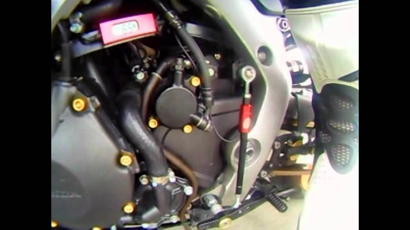
FIGURE A

The HM PLUS Quickshifter system in the order it is routed, left to right for underseat install of the LCD module. The paired connectors from the HM loom correspond to stick coils of cylinders #1 through #4. The single connector lead [LCD] couples with the yellow ribbed male connector from the LCD module.
There is also a small ground wire [G] that comes out of the LCD wire at the yellow ribbed connector.
For routing of the LCD wire on the left side of the motorcycle, the loom leads may be connected right to left (reverse order of the photo).
Loom Installation
4. Stretch the loom across the top of the engine. The inline connector leads on the loom are grouped in pairs. Refer to FIGURE A, above . Arrange the first pair of inline leads [1] near the stick coil to cylinder #1 on the far left side of the engine top. Arrange the second pair of inline connectors [2] near the the stick coil of cylinder #2, the third pair of inline connectors [3] near the stick coil of cylinder #3 and finally, the last pair of inline connector leads [4] near the stick coil of cylinder #4 on the far right side of the motor top. The single lead [LCD] hangs out to the right side of the bike.

5. Connect each of the OEM female fasteners from the grey tape wrapped engine wire to the corresponding HM loom male fasteners.
6. Connect each of the HM loom female fasteners to the corresponding OEM male connector on the stick coil. The Loom is now connected inline of the stick coil wires.


OPTIONAL: Using cable tie mounting plates and 4” zip ties, the grey engine wire may be hung from the underside of the air box above the engine. This will create a more organized arrangement of wires on the engine top while the the loom will rest on the engine cover over the stick coils.
LCD and Wiring Installation
7. Remove fuel tank (see Fuel Tank Removal).
8. Remove the fuel tank bracket and Mudflap bracket (see Fuel Tank Bracket and Mudflap Bracket Removal, steps 1).
9. Open the retainer rings below the fuel tank support.

10. Place the LCD module in the underseat compartment as far to the left and as
far forward as possible. Secure the LCD with small, self adhesive backed velcros on the bottom of either end.
FIGURE B

This is the LCD and wiring installed in my bike. The module was placed on top of the Power commander because There was not enough wire on the Power Commander or the LCD to locate either farther away.
For steps 11 through 13, refer to FIGURE B above
11. Route the flat wire from the LCD under the fuel tank and to the right side of the fuel tank compartment. The flat wire should pass under the fuel tank support [A] and the undertail support [B]. The flat wire should also pass under the black taped bundle of wires [C] that were held in the retainer rings.
12. Affix a self adhesive zip tie mounting plate [D] in the bottom of the fuel tank compartment and loosely secure the flat wire to it with a 4” zip tie.
13. Continue to rout the flat wire toward the front of the bike passing it under the metal retainer [E] at the front bottom right of the fuel tank compartment. Slide the connector lead under the battery compartment and over the engine mount so that the lead comes out in the back of the engine compartment. The lead connector should reach the area where the ground screw for the battery is located.
14. Push together the lead connector from the loom to the yellow ribbed lead connector from the LCD until the lock engages.

Tuck the leads neatly behind the battery ground screw at the front of the battery box. The wire to the loom is routed between the black and grey leads on the throttle bodies. Use an 8mm socket to remove the battery negative ground screw and attach the ground wire that comes out near the male connector lead on the flat wire from the LCD.

15. The wire from the LCD to the strain gauge is routed along the left side of the fuel
tank compartment. Thoroughly clean the underside of frame rail with an alcohol pad. Attach a couple of cable tie mounting plates and loosely secure the wire from the LCD to the strain gauge with 4” zip ties.

16. Free up the main wiring bundle on the left side of the bike so that it may be moved for easier routing of the shifter wiring. Use wire cutters to cut the factory installed zip tie that retains the large bundle of wiring on the left side of the fuel tank. Be careful not to damage the wires.

With a 10mm wrench, remove the wire retainer bracket from the sub frame section on the left side of the bike.

Use a 10mm wrench to remove the wire retainer/fairing bracket from behind the left ram air tube.

17. Wrap the strain gauge sensor in masking tape so that its finish will not be damaged.

18. Begin a guide line using two feet of string tied to a 7” ziptie. Start by threading the ziptie from the fuel tank compartment and under the battery compartment. Make sure that the path passes under ALL hoses and wires.

In order for the sensor wire to be drawn over to the left inside of the frame, the guide line needs to be routed under all hoses and wires.

The path of the guideline should pass under all hoses and wires and over the engine mount. The 7” ziptie guide has been marked with yellow dots.

The ziptie should exit into the engine compartment, passing over the engine mount.
19. Pull the sensor and wire under the fuel line and all wire bundles that are routed on the left side of the fuel tank compartment.

Sensor and Shift Rod Installation
20. Tie the free end of the guideline around the front of the strain gauge sensor. There are two flanges at the tip that create a small neck that the tie will not slip off of.

21. Draw the zip tie through so that it hangs down near the side stand mount. Gently pull the strain gauge sensor through using the other hand to push. DO NOT FORCE. The path is very tight for the strain gauge sensor.

The strain gauge is sensitive to compression and traction. Pulling the wire can cause damage and void the warranty. I was very careful to coax the sensor through, pulling aside other wires and tubes that the sensor wire is routed under.
22. Pull the fuel line aside being careful to not kink it. Lift the large bundles of wire on the left side of the fuel tank compartment and slide the strain gauge sensor wire under them and the fuel line.

Carefully slide the sensor wire (closest to the frame in pic) under all wires and tubes so that it is drawn back over to the left side of the fuel tank compartment right next to the frame.

Lift the large grey taped bundle of wires on the left rear of the engine compartment and slide the strain gauge sensor wire between it and the engine mount. Slide the sensor wire all the way over to the left. Let the sensor hang down near the shift rod linkage.

23. Place the fuel line back under the retainer being careful to not kink or dent it. Replace the factory ziptie that was cut in step 12 with a new 7 in ziptie. Use a 10mm socket and an 8mm socket to reinstall the brackets to the frame that were removed in step 13.
Sensor and Shift Rod Installation
24. Thread the studs included with the HM shifter into each end of the strain gauge sensor. Use a 3mm allen wrench to gently snug them against the bottom of the threads in the strain gauge. Take care to tighten them only enough so that they will stay put. Also thread a stud intothe shift lever rose joint. Thread a locknut onto each stud.

25. Remove the shift knuckle from the shift shaft with a 9mm wrench (see Vortex Rearsets Install step 31 and 32)and thread the rose joint onto the front stud of the HM shifter. Install the shift knuckle to the shift shaft. Use nonpermanent locking agent on the threads of the shift knuckle threads and tighten the bolt.

26. Thread a locknut and the new shift rod onto the back of the strain gauge. Thread a reverse thread locknut onto the shift lever rose joint and thread the shift rod on after it. Adjust the length of the shift rod so that the shift lever is at the proper height for your foot to shift up and down. This may take some experimentation and reassembly of the strain gauge and shift rod linkage. Tighten the locknuts on the shift linkage.

Normally, the shift knuckle would not need to be removed to install a shift linkage rod between the rose joints of the knuckle and the shift lever. Because the strain guage has a wire that would be wound up as the shift linkage was installed to the rose joints, the strain guage must be held stationary while the rose joints are are threaded onto it. The shift knuckle may also be removed to reposition the splines to help accommodate a longer or shorter shift rod.
I used a 115 mm rod which just barely fits my setup. I had to eliminate the rear lock nut and tighten the shift rod against the rose joint instead. A 100mm rod will work best for most setups.
For the underseat install, it is necessary to arrange the sensor with the wire to the back. For some other installations, the sensor may be arranged so that the wire points to the front. the sensor will work the same facing either directions.
Setup Adjustments
In order to change the settings for COMPRESSION/EXTENSION, SENSITIVITY and KILL TIME, the unit’s setup mode must be entered. To get the unit to enter setup mode, press and hold the small button on the back of the LCD. Turn the ignition on. The speedo/tach needles on the instrument cluster will sweep, the fuel pump will prime and the LCD display will power up, counting down 5-4-3-2-1-0. Release the button immediately after 1 and just as 0 is about to appear. If you wait to see the 0, you will not release the button in time to enter the setup mode. When the LCD is in setup mode, the display will flash.
The photos below show the kill time and sensitivity that were programmed into the shifter "for my bike." For all I know, HM might just program all of them with these settings.
Seno has been riding his 14r for some time and this is what he reported for his kill time/sensitivity preferences on a different thread:
" Did 60 miles thrashing on it and did not miss one shift. For the 14 with vortex rearsets, 80 sensitivity, 60-65 kill time seems to work very well. Obviously I am still testing this but from what I have seen so far, it is a very well made unit..."
COMPRESSION/EXTENSION
The first screen of setup mode displays:
C
E for compression and extension upshifting response
C for compression only or
E for extension only.

Choose which is appropriate for your shift pattern by pressing the button and releasing to switch from one setting to the next. (CE is not recommended by the manufacturer unless absolutely necessary)
SENSITIVITY
After COMPRESSION/EXTENSION is adjusted, press the button and hold until the LCD displays:
SENS ###%
The higher the number displayed, the more sensitive the sensor will be to compression and/or extension. It is recommended that extreme sensitivity be avoided so that accidental shifts do not occur. Chose a sensitivity that responds similar to the amount of force that is required to shift the gearbox without the quickshifter.
Press and release the button to change the sensitivity. 100% is the highest sensitivity. The display will roll back to 5% (the lowest sensitivity) after 100% is reached.

KILL TIME
Press and hold the button to display:
KILL ###ms
Kill times of 1ms-150ms may be chosen. 1ms is the shortest kill time interval and 150ms is the longest kill time interval. It is recommended by the manufacturer that the typical super bike with a slick gearbox will respond best to kill times of 65ms. Further, kill times that are too short may cause gearbox damage.

Setup is complete. The unit requires calibration but this is achieved automatically upon powerup and thereafter, continuously during operation.
To exit setup mode, press and hold the button until the LCD displays the normal screen.

Here is a picture of the setup I have recently changed to. The helmet lock was removed from the outside of the LH side frame and the module was mounted with velcro in its place. There is a bolt hole right under the module so that presents a good opportunity to fasten it more securely if necessary. The wire to the strain gauge was routed over the LH side frame and fastened with a zip tie mounting plate. tThe mounting plate was rounded out with a rat tail file so the wire would lay as low as possible. There is plenty of clearance for the mounting plate between the frame and fuel tank. The stick coil harness wire was routed straight up and then under the fuel tank bracket. I placed a piece of self adhesive weather stripping foam between the wire and the zip tie because I had to pull the zip tie a little tighter than I normally would to keep the wire from rubbing on the tail fairing. Fairings tend to vibrate a lot so I will have to keep a close eye on this to make sure the wire insulation is not being damaged. All other wire routing is the same as before.
AnniTori Shift Rod Measure Guide


Annitori Install Sheet


Weight Change
Part removed from Vortex Rearsets
Either the short Rod:
or the long rod:
Parts Added to Install HM PLUS
Either the 100mm HM shift rod:
or the 115mm HM shift rod (yes, the 115mm is lighter because of the reduced midsection):
HM PLUS quickshifter complete parts, studs and nuts:
This mod causes a small net weight gain:
6.1 oz (HM PLUS quickshifter with 115mm HM rod) - 1.75 oz (long Vortex rod) = 4.35 oz net weight gain.
6.25 oz (HM PLUS quickshifter with 90mm HM rod) - 1.55 oz (short Vortex rod) = 4.7 oz net weight gain
Other threads about the HM quickshifter.
* Last updated by: Rook on 9/3/2015 @ 7:12 PM *