


Wheels, Rotors, Sprocket and Axles Inspection
Runout tests are done on the axles, wheels, brake disks and rear sprocket to determine the amounts of warpage that has occurred to these parts from ordinary wear, overheating or damage from impact. Ideally, these parts will be perfectly straight or flat to provide optimum performance but there is a Standard Range of warpage that is considered acceptable when the parts are brand new. There is also a Service Limit to warpage. When the service limit is met or exceeded, the parts may be considered to be in need of replacement. The specs that I am using in this tutorial are from the ZX-14 service manual for the OEM parts only. Aftermarket parts sometimes have different warpage specs that should be obtained through the manufacturer of those parts.
In this tutorial, I am detailing the use of a wheel runout stand but if one is not available, the wheels may be left installed to the motorcycle and the wheels may be lifted off of the ground with a motorcycle jack or front and rear stands.
Special Tools
Wheel Runout Stand
A wheel runout stand holds the wheel aloft so that it can be rotated freely around its axis. The stand has cones that insert into the wheel bearings on both sides of the wheel hub (Do not over-tighten the cones, that could damage the wheel bearings). With the wheel axis held perfectly stationary by the cones, differences in measurements taken from the wheel will show the amount of warpage that is present in the part. Most wheel balancing stands (you will find many online for under $100) have a set of cones so that the stand may be used as a runout stand as well. Steel wheel balancing/runout stands work well with magnetic bases.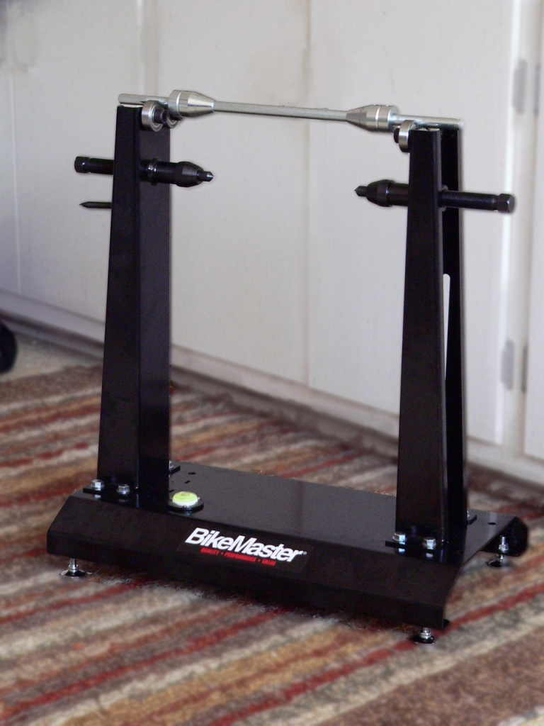
Magnetic Base
A magnetic base is a small stand used to hold a tool at a set distance from a surface. The magnetic base is equipped with a powerful, switchable magnet that is used to hold the stand stationary. Magnetic bases are also equipped with two beams and thumbscrew clamps to position the tool. There is also usually a thumbscrew on a spring to fine tune the distance the tool is set from the surface. You can pick up a magnetic base for about $10 at Harbor freight. I would avoid the kind that has a flexible steel tube instead of the two beams and thumbscrew clamps because it seems likely that the tube would bend during the runout test.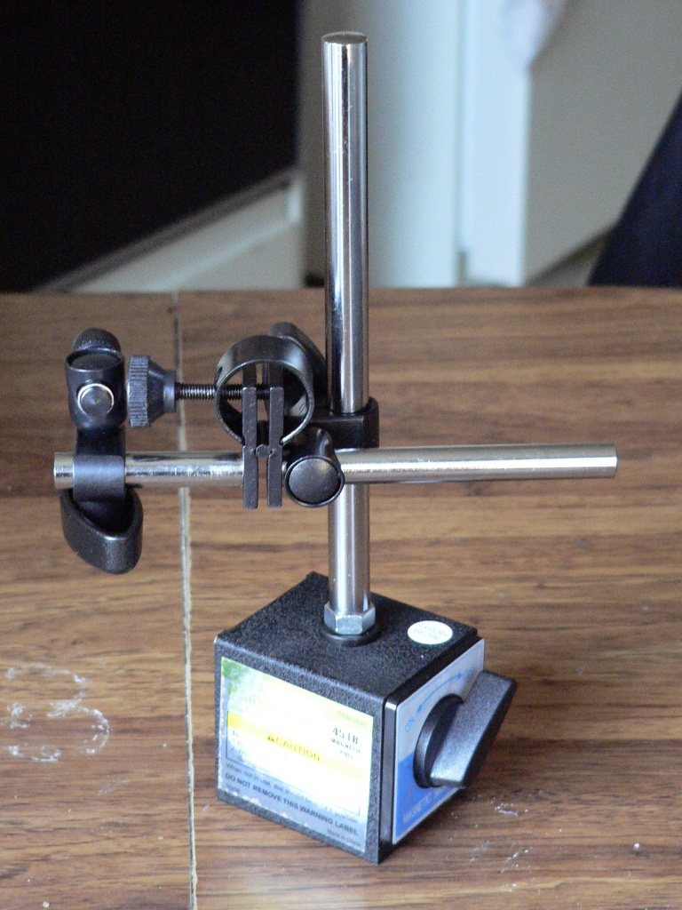
Dial Gauge
A dial gauge (also called a travel gauge)is used to measure very small distances in height along a surface. Dial gauges that measure one thousandths of an inch or smaller are available but they are probably quite costly. The ten dollar 0.00 in.-1.0 in. dial gauge I found at Harbor Freight was adequate for the do it yourself runout tests covered in this tutorial. For a home done inspection on more or less new, undamaged wheels, I have no problem estimating to within .005/inch with this gauge. It will be close enough. If you need to know within 10/1000ths of an inch, you need to acquire a more precise dial gauge.
On a 00.0~1.0” dial gauge, the main meter with the long needle indicates one-hundredths of an inch The small inset meter indicates tenths of an inch. A plunger stem protrudes from the bottom of the dial gauge. The tip of the stem rides along the surface that is being measured. A spring housed within the dial gauge compresses with the movement of the plunger stem causing the needles to move around the meter.
The dial gauge is fitted to a magnetic base. The beams of the base are adjusted to the proper height so that the tip of the plunger stem on the dial gauge will contact the surface to measured. Position the magnetic base so that the dial gauge plunger stem is compressed slightly against the surface and the meter reads about 0.00 inch. Once the dial gauge is positioned as such, turn the wheel 360 degrees until the lowest point on the surface is found. Calibrate the meter to 0.00 inches by using the fine tune thumbscrew on the magnetic base. Now you are ready to measure runout starting with the meter zeroed. 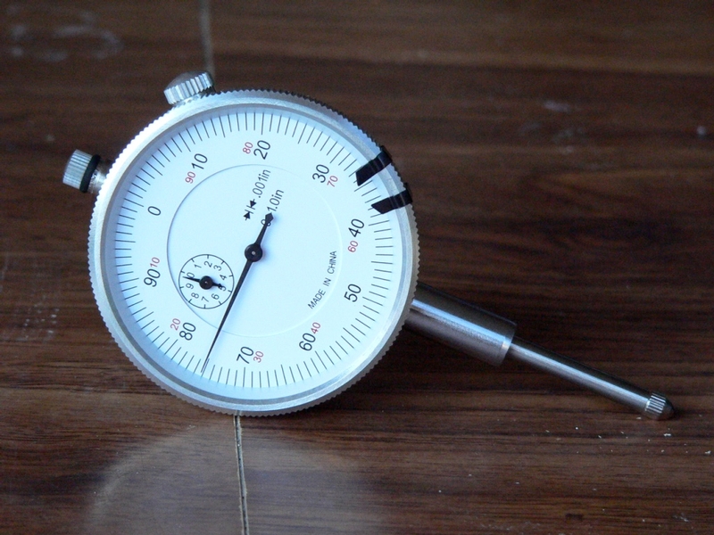
Micrometer
A standard unit micrometer with a flat anvil can be purchased at Harbor Freight for about $20. The one I bought has a 0~1 inch range and measures in increments of 0.001 inch. It is very easy to estimate to 0.0005 inch with this tool if necessary. It actually seems to be very accurate when tested with feeler gauge tapes. This tool is sufficient for most engine and mechanical parts that occasionally need measuring. The slipper ratchet knob on the back of the handle is great. Get one of those.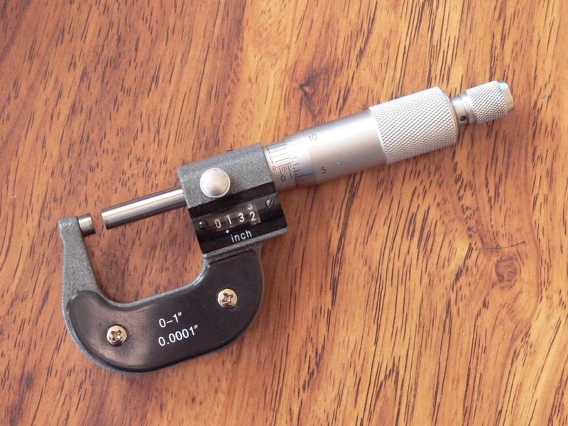
V Blocks
The v-blocks that I purchased were a cast and machined iron matched set and cost only five dollars plus nine dollars shipping. The machining looked and felt precise. You can find inexpensive blocks such as these if you search on Amazon and Ebay.
The blocks I got were one and a half inches high. I softened over all edges with 220 sand paper to eliminate any burs that may have been present.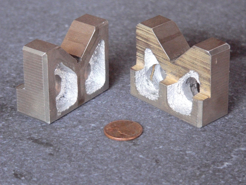
Surface Plane
A surface plane is just a very flat surface that is ideal for measuring height accurately. It is a good surface to place V blocks when conducting runout tests. You might get by using an ordinary table top but a surface plane will make you more confident of your measurements.
The surface plane I bought was purchased on Ebay from a company called Woodcraft. It cost $25 which was a great deal. It is marble and comes with a report which claims precision within .001mm/m. The size is 11 7/8” x 9 1/8” which is barely large enough for some uses that one will encounter when doing runout tests on engine parts but for the price, you can’t beat it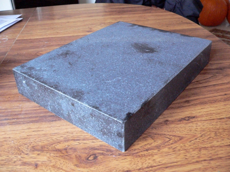
Tools:
tire pressure gauge
tread depth gauge
front and rear stands
tape
rag
kerosene
bearing grease
wheel runout stand
dial gauge
magnetic base
micrometer
V blocks
surface plane
Tire Inspection
1. Remove the tire valve caps. Use a tire pressure gauge to inspect the front and rear tires for proper air pressure. The tires need to be absolutely cold when checked. Inflation pressure varies according to rider preference but 42 psi is usually the recommended tire inflation pressure for both the front and the rear tire.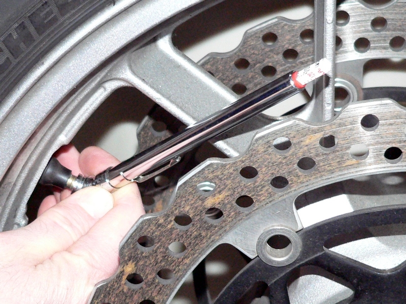
2. Visually inspect the tire for cracks cuts or foreign objects puncturing the tread. If any such damage is found, replace the tire. Consider replacing a tire if it is over one year old.
3. Inspect the tread wear of the tire by observing the wear bars in the tire sipes. If any of the wear bars are level with the tread, replace the tire. 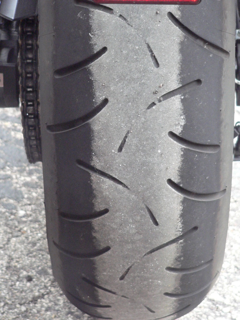
This tire was long overdue but you can see where the wear bars in the sipes are level with the tread.
You may also use a tread depth gauge to measure the tread wear. Use the tread depth gauge to measure the tread depth where the tire has worn the most (usually the center). Measure the tread depth at several points around the tire. If any measurements are less than the specced service limit, replace the tire. 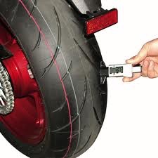
Tread Depth
Front, Standard: 0.15 in. (3.8mm)
Front Service Limit: 0.04~0.06 in. (1.0~1.6 mm)
Rear, Standard: 0.19 in. (4.8 mm)
Rear, Service Limit: 0.08~0.12 in. (2~3 mm)
Wheel Bearings Inspection
4. Lift the bike on front and rear stands.
5. Turn the wheel and visually check for cracks dents or warpage in the wheel. If any such damage is discovered, replace the wheel.
6. Twist the front wheel left to right to check for slop between the bearing and the axle. Spin the front wheel slowly to check for roughness, binding or noise. It’s normal to hear some noise from the brake rotors dragging the pads. If roughness, binding or noise is detected, remove the wheel to check the bearing (step 9 of this tutorial). 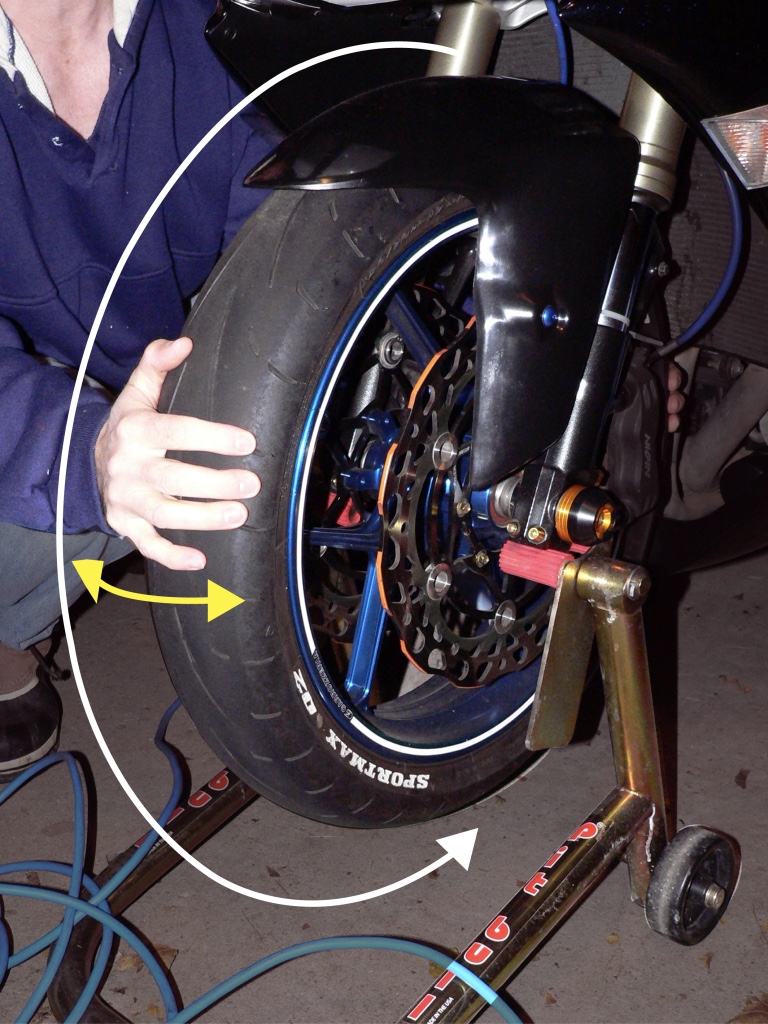
A fork stand is preferred to hold the steering fast while the front wheel is twisted left to right If a steering pivot stand is used turn the handle bars to full lock left or right so that the steering is held fast.
Repeat the same procedure for the rear wheel.
7. Lower the motorcycle off of the stands.
If the tires, rotors or sprocket are being replaced, the front and rear rotor bolts and the sprocket nuts should be broken free at this time (refer to Front and Rear Brake Disk Removal, step 1 and 2 and Sprocket and Drive Chain Replacement, step 9). Just turn the fasteners a degree or two so that all parts remain firmly in place against the wheel.
8. Remove wheels (see Front and Rear Wheel Removal, steps 1 through 9 and steps 20 through 32).
9. Turn the bearing on each side of the wheel back and forth by hand. Feel for play, roughness or binding. Also check the bearing seal for cracks or leakage. Replace the hub bearing if it does not turn smoothly or if the seal is leaking or damaged. 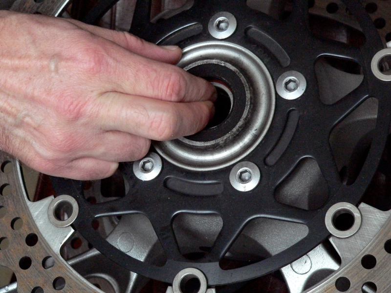
Coupling Inspection
10. Mark the coupling and wheel hub with tape so that they may be reassembled exactly as they were separated. Remove the coupling by lifting under the sprocket with both hands while pressing down on the edge of the wheel hub with thumbs. The coupling slides up out of the wheel hub.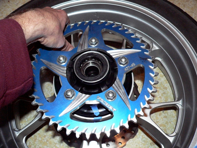
11. Remove the collar. It will either stick to the wheel bearing in the wheel hub or it may stick inside of the coupling. Wipe grime from the collar and flat surfaces of the coupling with a rag damp with kerosene. Be careful not to allow the solvent into the bearing.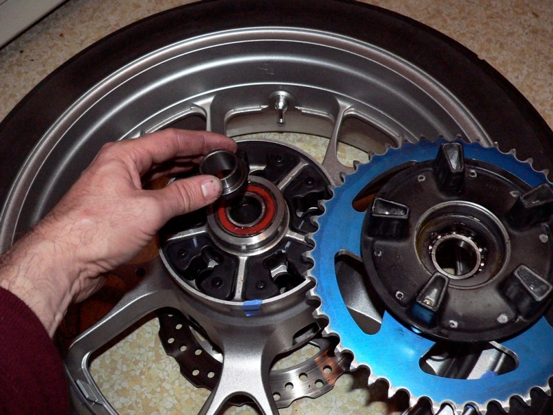
12. Inspect the coupling bearing for rough or sloppy movement. If the coupling bearing does not operate smoothly, it should be replaced with a new bearing.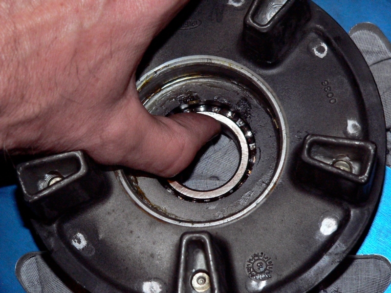
13. Pack the coupling bearing with bearing grease and turn the bearing to work the grease into the bearing.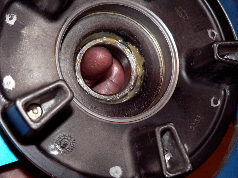
14. Inspect the coupling dampers for wear or deterioration and replace them if any are not in good condition. Clean the dampers and each cell with a damp kerosene rag.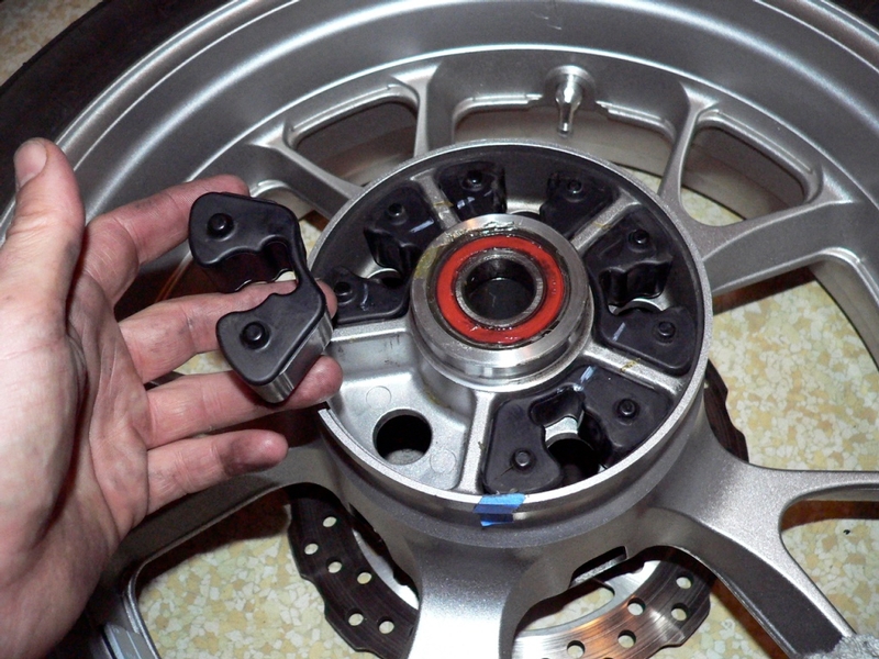
15. Reinstall the Coupling collar. 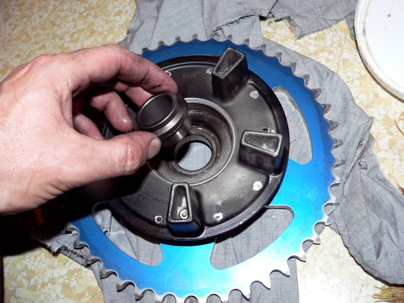
16. Reinstall the coupling to the wheel hub aligning the tape marks made in step 10.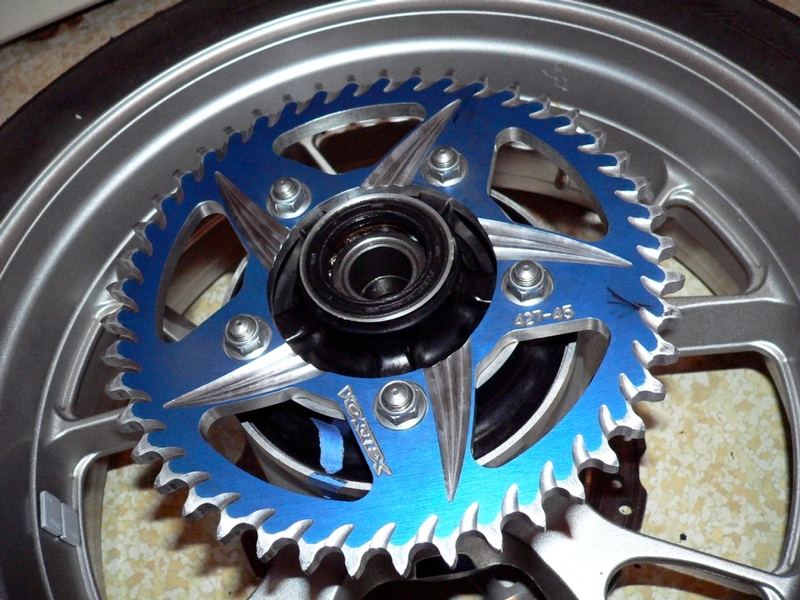
Rotor and Sprocket Inspection
17. Place the wheel on a wheel runout stand.
18. Place a dial gauge fitted to a magnetic base against the surface of the rotor where the brake pads contact. Watching the dial gauge, turn the wheel one full rotation to find the lowest point on the the rotor. Use the fine tune thumbscrew of the magnetic base to calibrate the dial gauge to 0.00 inches at the lowest point on the rotor.
19. Turn the wheel one full rotation taking careful note of the highest spot measured in the rotor by the dial gauge. The difference between the lowest spot (0”) and the highest spot is the warp.
Use the same procedures to measure runout in the front rotors and the rear rotors. The warp spec is also the same for both front and rear rotors. Replace rotors that exceed the 0.01 specced warp (seeFront and Rear Brake Disk Removal).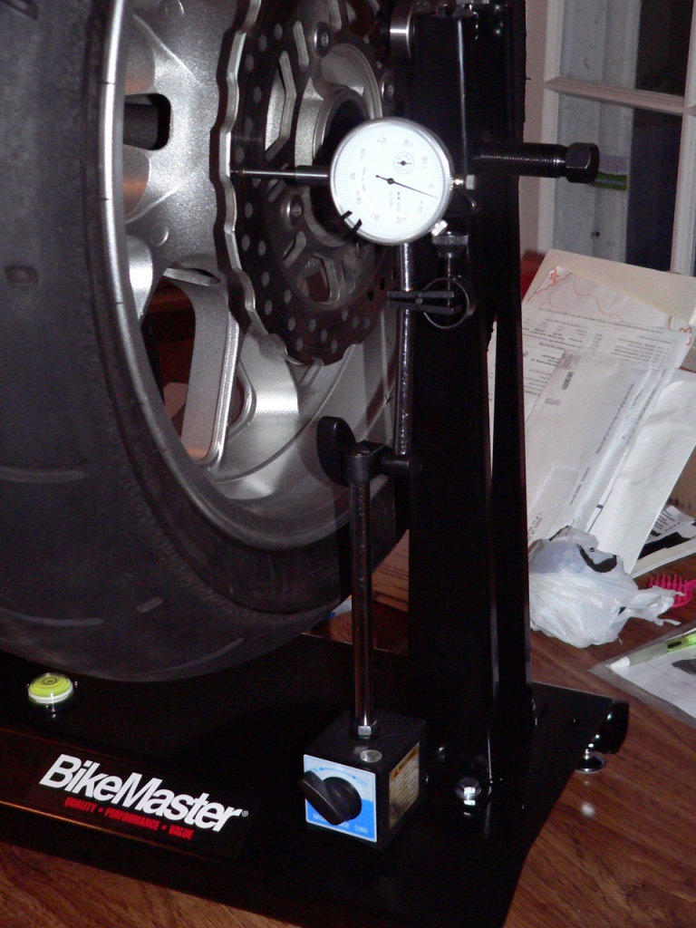
Standard: TIR 0.006 in.or less (0.15 mm)
Service limit: TIR 0.01 in. (0.3 mm)
20. Use a micrometer to measure the thickness of the rotors where they have been worn the most by the brake pads.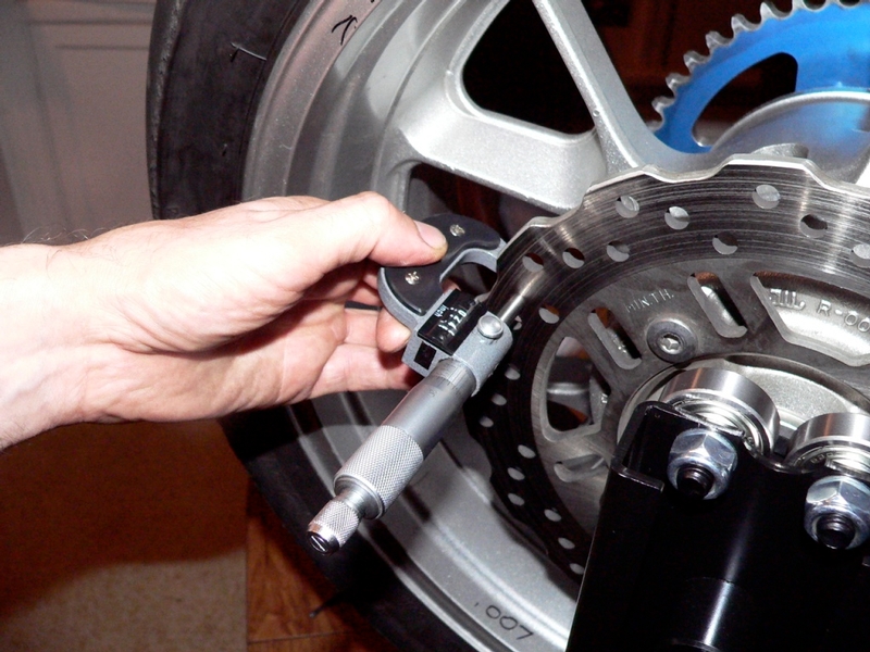
Front Brake Disk Thickness
Standard: 0.19 ~ 0.20 in. (4.8 ~ 5.2 mm)
Service Limit: 0.18 in. (4.5 mm)
Rear Brake Disk Thickness
Standard: 0.23 ~ 0.24 in. (5.8 ~ 6.2 mm)
Service Limit: 0.22 in. (5.5 mm)
Replace the rotor if it has worn past it’s service limit (see Front and Rear Brake Disk Removal).
21. The procedure for the sprocket runout test is the same as the rotor runout test (steps 17, 18 and 19 of this tutorial). 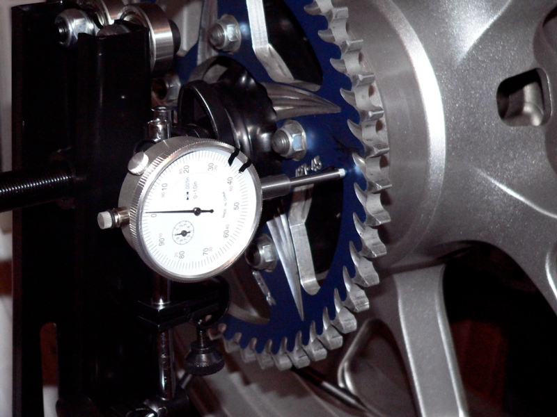
Rear Sprocket Warp
Standard: TIR 0.016 in. (0.4 mm) or less
Service Limit: TIR 0.020 in. (0.5 mm)
22. Visually inspect the rear sprocket for wear and damage. Check if any teeth are broken or worn as shown in the diagram below [A and B] or if the space between teeth seems excessively wide.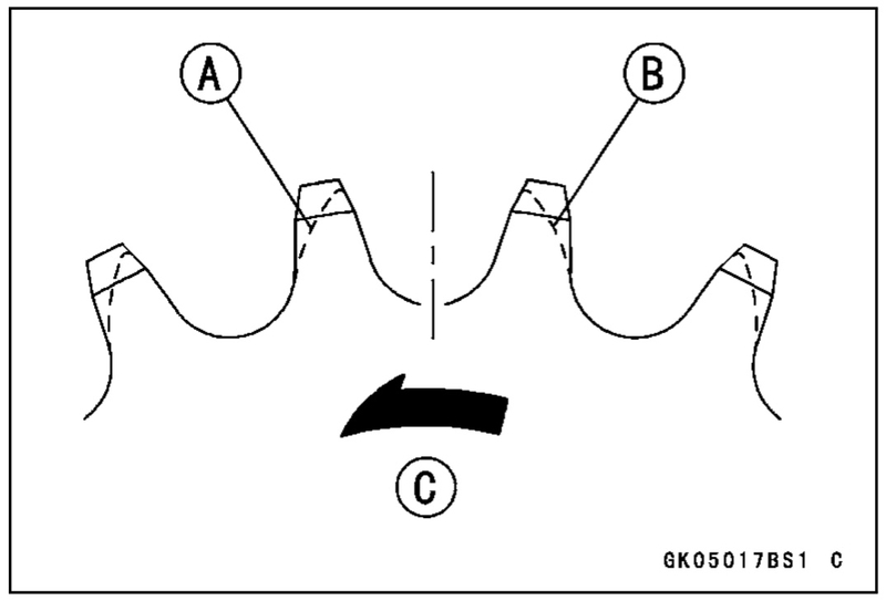
If the sprocket is worn excessively or if the warp is more than .02 inches, replace the sprocket (see Drive Chain and Sprocket Replacement, steps 9 through 11 and step 35).
If the tire is in need of being replaced, it should be removed (see Tire Removal and Mounting, steps 1 through 14) before proceeding with the wheel inspection.
Wheel Runout Tests and Balance
The sprocket and rotors interfere with perpendicular positioning of the dial gauge for wheel runout tests. It’s necessary to remove the rotors and sprocket to conduct these tests however, if the tire is removed from the rim, the inside surface of the wheel may be used to test wheel runout (see pics in step 26, below).
RECOMMENDED WHEN THE TIRE IS NOT REMOVED FROM THE WHEEL:
Remove sprocket (Drive Chain and Sprocket Replacement, steps 9 through 11)
Remove front and rear rotors ( Front and Rear Brake Disk Removal, steps 1 through 4).
23. Place the rear wheel on a wheel runout stand.
24. Attach the magnetic base fitted with the dial gauge so that the plunger stem touches the outside surface of the rim. Watching the dial gauge, turn the wheel one full rotation to find the lowest point on the the rim. Use the fine tune thumbscrew of the magnetic base to calibrate the dial gauge to 0.00 inches at the lowest point on the rim.
25. Turn the wheel one full rotation taking careful note of the range of warp that is measured in the rim by the dial gauge. Both sides of the rim should be checked. The maximum measurement found is called the axial runout.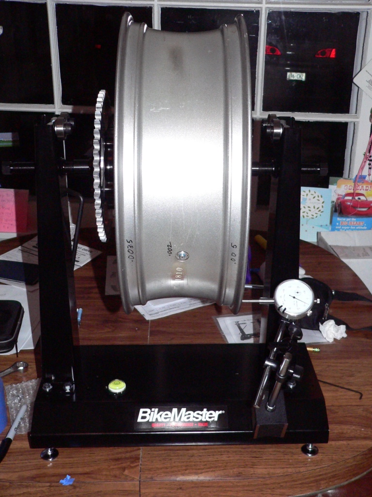
26. Reposition the Magnetic base so that the dial gauge contacts the horizontal surface of the wheel. You may position the magnetic base so that the plunger stem touches the outside of the wheel or the inside. 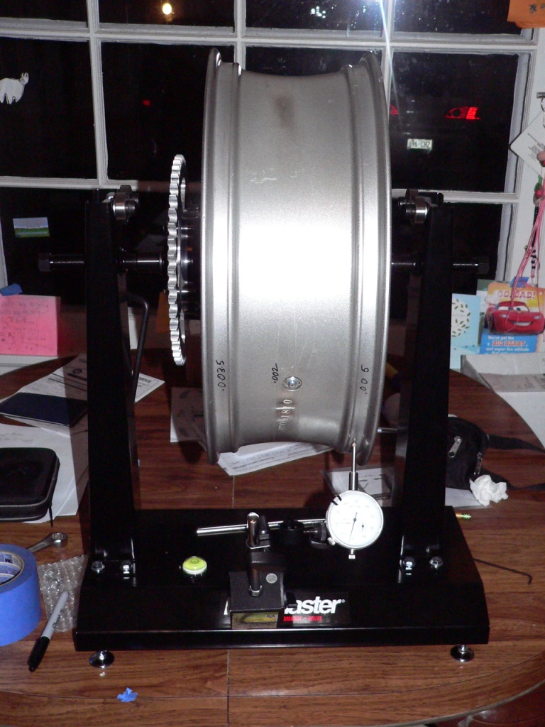
I found it more convenient to measure wheel runout on the inside of the wheel.
Test both left and right sides of the wheel. The difference between the highest spot on the wheel and the lowest spot is called the radial runout.
Standard:
Axial TIR 0.5mm (0.02 in.) or less
Radial TIR 0.8 mm (0.03 in) or less
Service Limit:
Axial TIR 1.0mm (0.04 in.)
Radial TIR 1.0mm (0.04 in.)
If the wheel runout exceeds the service limit spec, check the wheel hub bearings (step 9 of this tutorial). If the excessive wheel runout is not caused by bad bearings, replace the wheel.
27. Balance the wheel (refer to Wheel Balance, steps 5 and 6 only for wheels with tires that are NOT being replaced. Refer to Wheel Balance, steps 1 through 6 for wheels with old tires that have been removed for replacement).
Axle Inspection and Runout Test
The procedure is identical for the front and rear axle.
28. Visually inspect the axle for cracks or bends. Replace the axle if any damage is found.
29. Place V blocks 3.94 inches (100 mm) apart atoop a surface plane. Rest the axle in the V blocks. Place a dial gauge on the axle above the center point of the blocks.
30. Gently turn the axle 360 degrees in the V blocks to find the lowest point. Zero the dial gauge as described in step 5 or step 12 of this tutorial.
31. Turn the axle 360 degrees. The highest reading on the dial gauge is the axle runout. If the axle runout is more than .008 inches (you will have to look closely at you 00.0~1.0 inch dial gauge to estimate), replace the axle. 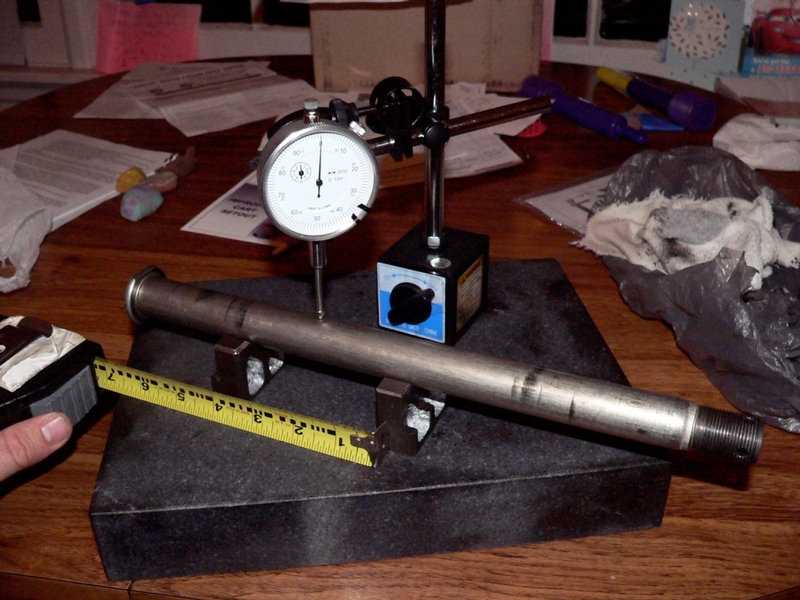
Axle Runout / 3.94 inch (100 mm)
Standard: TIR 0.0012 in. (0.03 mm)
Service Limit: TIR 0.008 in. (0.2 mm)
Install tires to the wheel if the tires are being replaced (refer to Tire Removal and Mounting, steps 15 through 22 and steps 23 through 40).
Install the wheels to the motorcycle (refer to Wheel Removal and Installation, steps 10 through 19 and steps 33 through 44).
Torque all sprocket nuts (refer to Sprocket and Drive Chain Replacement, step 35) and rotor bolts (refer to Front and Rear Brake Disc Removal, steps 5 through 8).
* Last updated by: Rook on 3/12/2018 @ 8:54 PM *