


PC5 Underseat Install
There is nothing wrong with installing your PC on the ram air tube as recommended in the instructions included with the PC5. I’ve always liked the look of electronics under the seat however, and I feel it is a little safer from dust and moisture. It is also easier to access modules when they are positioned under the seat. Installing under the seat is more work than installing at some other position on the left side of the bike closer to the main wiring harness.
This procedure was done with the PC5. I believe some owners have positioned the PC3 under the seat so this same procedure may work for the earlier unit as well. It was an extremely tight fit for the PC5 which is somewhat smaller than the PC3. Also, the wire on the PC5 was just long enough to allow it to reach the back seat compartment. If an Ignition Module is installed, it must be connected to the PC5 but the Ignition Module harness will not reach under the seat without modification. However, the PC5 is now available with ignition mapping and fueling mapping so a separate ignition module is not necessary.
It will be helpful to look carefully at the connectors on the PC5 to familiarize yourself with how they work. Look at the catch and all of the small connections inside the connectors. Look at the ridge along the edge opposite of the catch. You will know what you are up against when you disconnect the throttle bodies subharness. The PC5 connectors are identical to the connectors throttle bodies subharness.
Do First:
Remove the Seat
Prop the front of the fuel tank (see FUEL TANK REMOVAL, steps 1 and 2)).
Disconnect the Throttle Bodies sub harness leads (see steps 1 and 2, THROTTLE BODIES SUBHARNESS REMOVAL).
Tools and materials you will need:
1 1/2" blue painter’s tape
mill file
8mm socket/ratchet
two 4” zip ties
two zip tie mounting plates
PC5 Routing
1. Apply 1 1/2" blue painter’s tape to PC5. This will protect the finish of the unit during the procedure and it will come off of the paper sticker without damaging it. I would not use regular masking tape for this.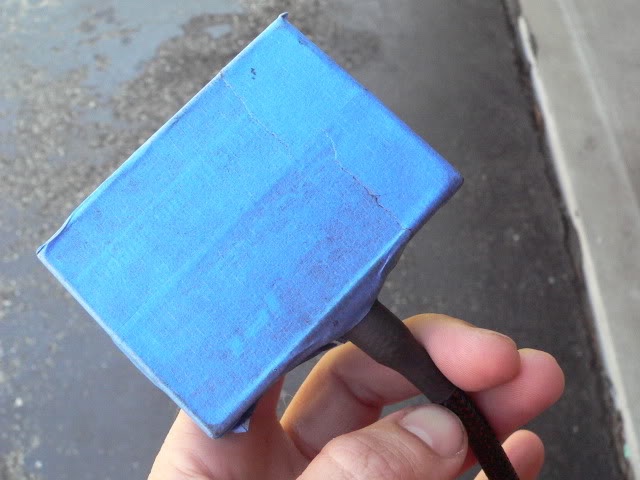
2. The goal is to get the PC5 over to the left side of the bike but it will not fit through the frame on that side. It must be drawn through from the right side of the bike.
Pull aside the negative battery cable. Push the PC5 over the top of the cable and through the thin space on top of the engine and under the fuel tank compartment. Make sure that you slide the PC5 on top of, not under, the rubber engine insulator matt. This is a very tight fit but it will go through. Do not turn the PC5 sideways and kink the wire. It will push through exactly as shown in the pic. Take your time and don’t force it. 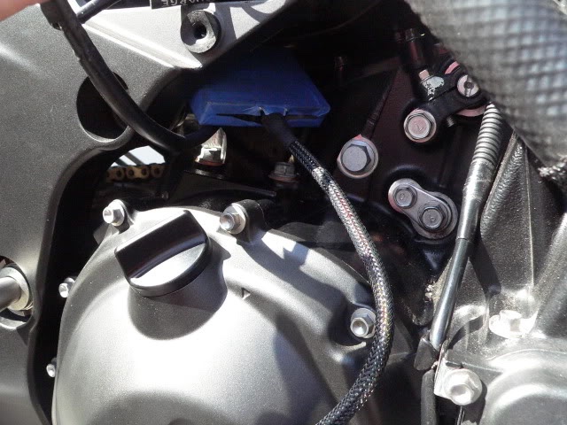
3. The PC5 will come out in the fuel tank compartment. Now it must be worked over to the left side. I found it helpful to remove the screws that hold the lid to the back wall of the battery compartment as shown in this pic. That allowed me to move aside some of the wiring that was in the way.
The wire on the PC5 should be routed right over the fuel line which is shown at the bottom of the pic.
Pull the PC5 into the fuel tank compartment for now. 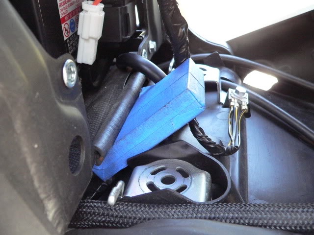
PC5 Connection
4. Feed the grey lead connectors from the PC5 wire over the rubber insulator mat and across to the left side of the engine compartment.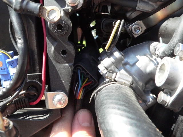
5. Pull both plugs out of the left side of the motorcycle. 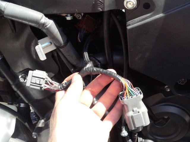
6. Push the grey male lead connector from the PC5 harness into the brown female receptacle of the throttle bodies subharness which remains bracketed inside the engine compartment.
Make sure you press the lead connectors together until you hear a click. A little bit at a time, this is not fast work. No click, no latch, plug will vibrate apart on you when you are riding, engine will die. So make it click. 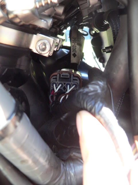
7. Next connect the grey female receptacle on the PC5 harness to the brown male lead connector of the throttle bodies subharness.
Press them together and listen for the click. 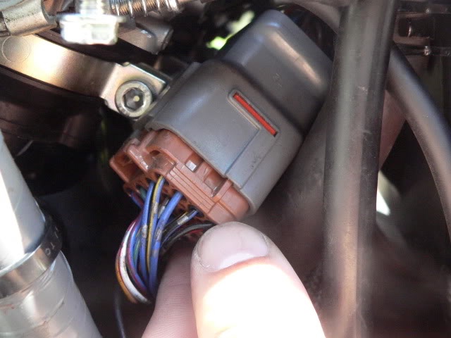
8. Locate the screw hole where the main wiring harness retainer bracket was attached to the frame (my thumb points to the screw in this pic). This will serve as the ground for the PC5.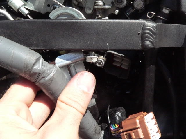
9. Use a mill file to remove paint from the frame on the bump around the screw hole. This should give you a good ground, but it looked to me like the threads in the hole were bare metal as well. 
Put the retainer bracket back on fastening the the ground wire eye terminal at this location (reverse of step 1, THROTTLE BODIES SUBHARNESS REMOVAL).
Put the retainer bracket screw through the bracket and the ground wire eye terminal and tighten it using an 8mm socket/ratchet.
PC5 Mounting
10. Pull the PC5 to the under seat compartment where it will be positioned. The PC wire is just long enough but it will reach. 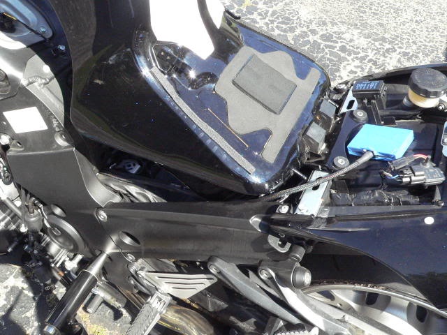
11. Prop the back of the fuel tank (see FUEL TANK REMOVAL, step 2, To prop the back of the tank).
Remove the fuel tank bracket from the frame and reinstall it over the PC5 wire (see FUEL TANK AND MUDFLAP BRACE REMOVAL, steps 1 and 2.
Remove the sheet from under the fuel tank.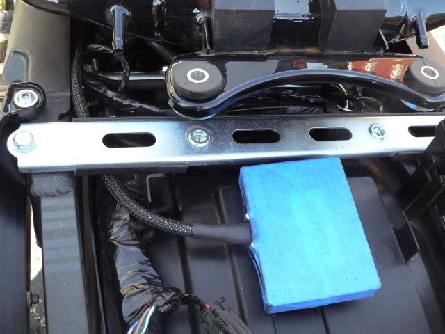
12. Loosely attach a zip tie and mounting plate to the PC5 wire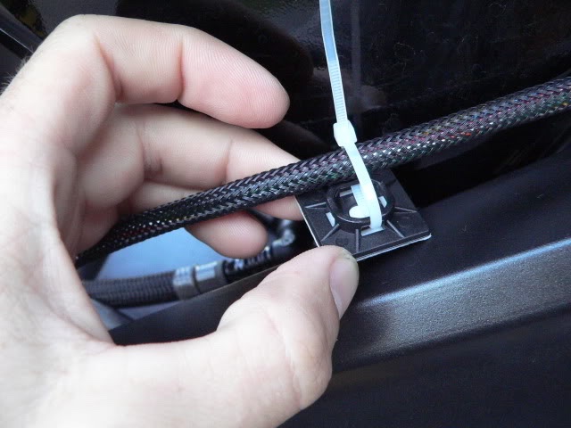
13. Remove the backing from the mounting plate and stick the mounting plate under the top surface of the frame inside the fuel tank compartment.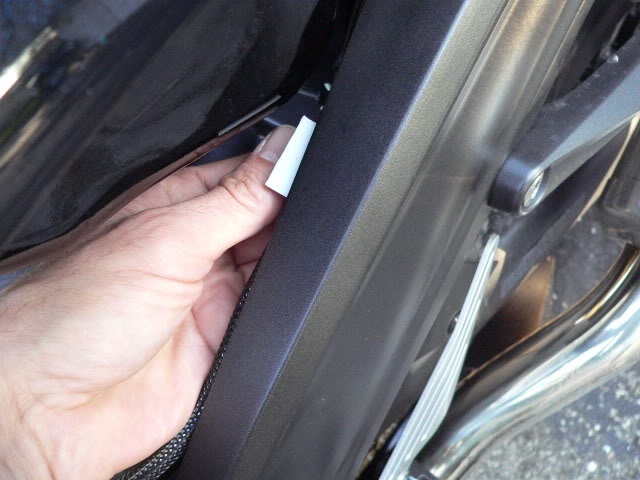
14. Attach a mounting plate in the same way to the inside of the frame under the cross piece which supports the back of the fuel tank.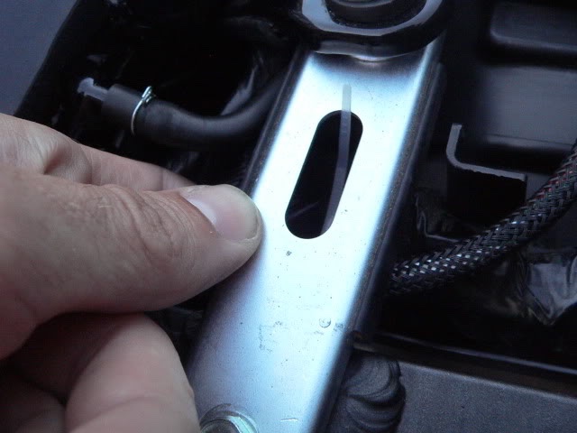
15. Determine exactly how you want to position your PC5 (there is not a great deal of leeway considering that you have just enough wire).
Remove the blue painters tape.
Remove the backing from the hook velcro supplied with the PC5 kit and apply to the back of the PC5.
Attach the eye velcro to the hook velcro and remove the eye velcro’s backing.
Stick the velcro to the mudflap so the PC5 is positioned properly.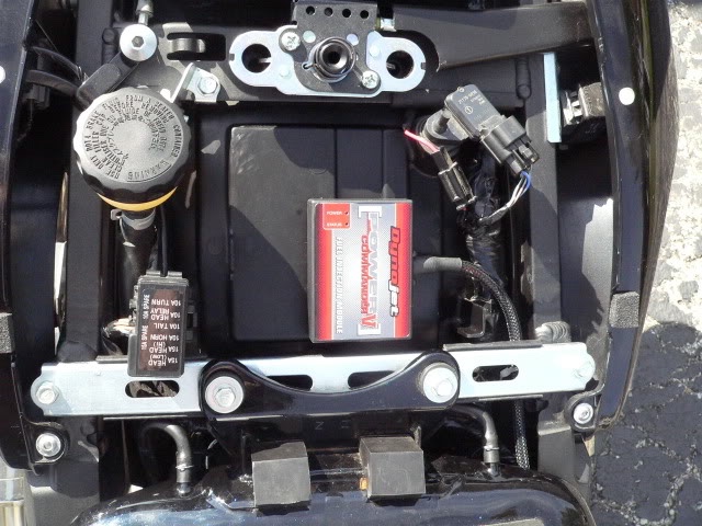
Connect the battery negative ground screw to the frame (see BATTERY REMOVAL, step 5).
Start the motorcycle to test the connection of the PC5. If the bike starts and continues to run, all is good.
Install the fuel tank (see FUEL TANK REMOVAL, steps 7 through 10).
Install the seat
Install the Main Wiring Harness bracket (see step 1, THROTTLE BODIES SUBHARNESS REMOVAL).
Install the coolant reservoir (see ENGINE COOLANT RESERVOIR, step 3).
Install the fairings (see FAIRINGS REMOVAL).
To use your PC5, see HOW TO LOAD MAPS AND AN OVERVIEW OF PC5 SOFTWARE.
Removal
Do all the DO FIRST procedures linked at the beginning of this tutorial.
Removing the PC5 from the undersea compartment is basically the reverse procedure of installation. It seemed best to turn the module and push it under the back of the battery compartment with the PC5 wire pointing backward so it would not interfere with the starter.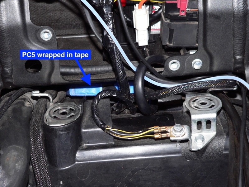
Then slide it across and down between the underside of the battery box and the engine mount.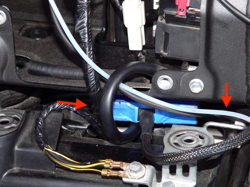
Reconnect the stock main wiring harness to the throttle bodies subharness and complete the other finishing procedures.
* Last updated by: Rook on 1/28/2018 @ 11:44 AM *