


External Shift Mechanism Removal and Inspection
EVO Shift Star Install
You may need to remove the shift pedal and / or shift shaft to replace them in the unfortunate event of a crash or to install a shift knuckle for rearsets or aftermarket shift star. The shift shaft may also require to be removed to straighten or replace it if it or it’s pedal serrations become worn out.
It will be easier to remove the gear positioning arm (see step 6) with the transmission in gear rather than in Neutral.
Here are a few threads about the shift star installation.
Evo Shift Star???
EVO Shift Star Question
SHIFT SHAFT WON’T COME OUT
Do First:
REMOVE CLUTCH COVER
REMOVE CLUTCH PLATES
REMOVE CLUTCH HUB AND BASKET
Tools:
10mm socket and 3 inch extension
Sharpie marker
WD-40 and a clean
lint free rag
circlip pliers
5 mm hex tool bit
Removal
1. Neutral will put a bit more tension on the gear positioning lever spring so put the transmission in first or second gear if you intend to remove the gear positioning lever (step 6).
Use a 10mm socket and 3 inch extension to remove the bolt that secures the OEM shift pedal to the shift shaft. The bolt passes through a groove in the end of the shift shaft (see pic, step 9). You must remove the bolt completely from the clamp in order to slide the pedal off of the serrations on the shaft. 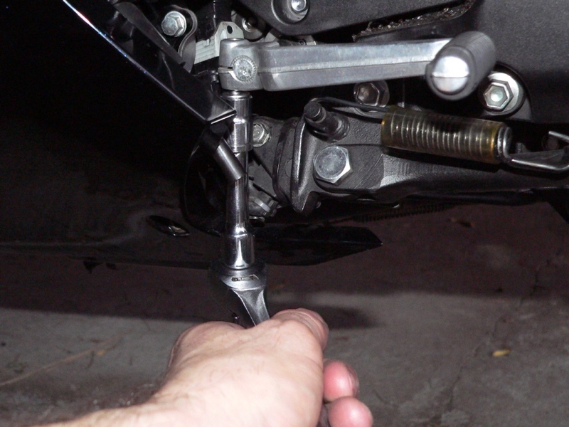
2. There is a small dot for pedal positioning stamped on the end of the shift shaft. Carefully note the position of the shift pedal for reinstallation reference. I suggest marking the pedal and shaft with a Sharpie marker.
Remove the shift pedal. 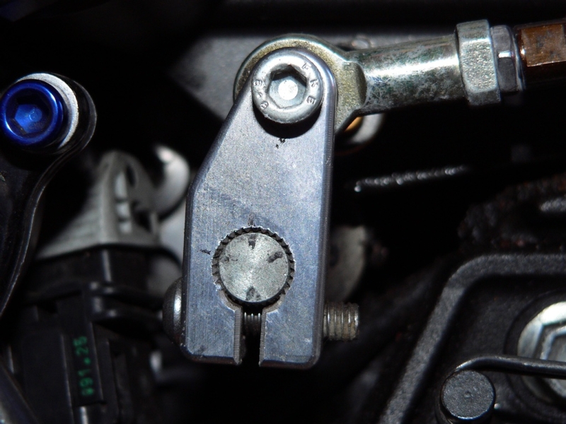
This photo shows how I mark my shift linkage knuckle on my aftermarket rearsets. Taking a closeup photo of the parts’ position is a foolproof way to reinstall the pedal at the height it was at when removed.
3. Use WD-40 and a clean, lint free rag to thoroughly clean dirt and grease from and around where the shift shaft protrudes from the crankcase.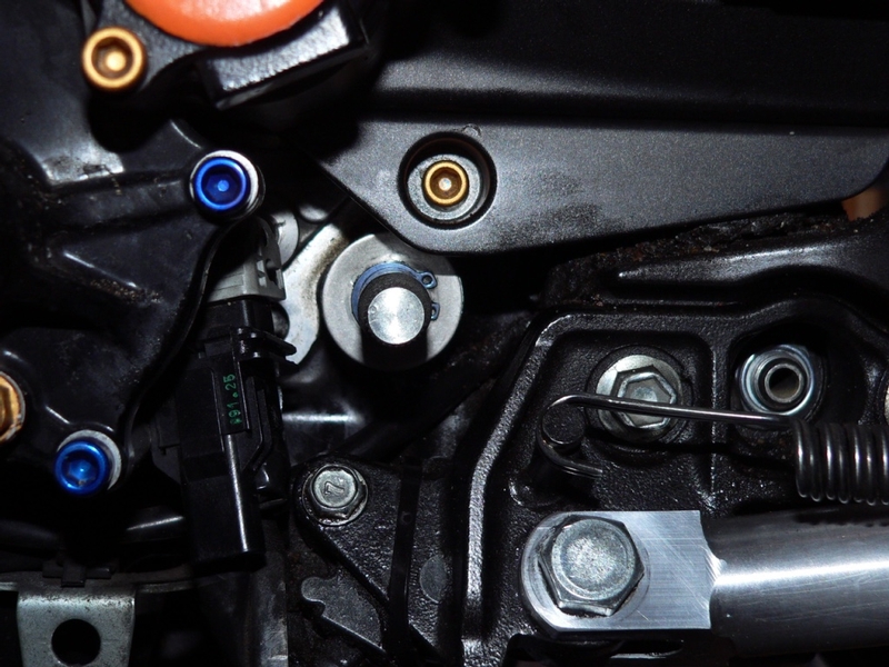
4. Use a circlip pliers to remove the snap ring from the shift shaft.
There is an external washer behind the snap ring. It will probably remain stuck over the shift shaft tunnel. There is an oil seal and needle bearing inside the shift shaft tunnel under the external washer.
Clean any remaining grime from the shift shaft.
5. Be sure to have the bottom of the clutch compartment covered with a clean sheet of plastic in case any small parts drop. 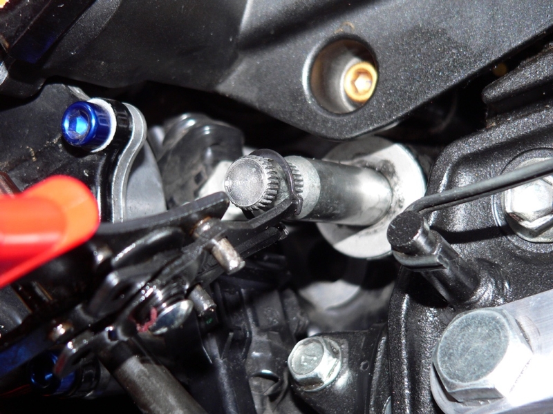
Go to the RH side of the bike and gently pull the shift shaft mechanism arm laterally to slide the shift shaft out. 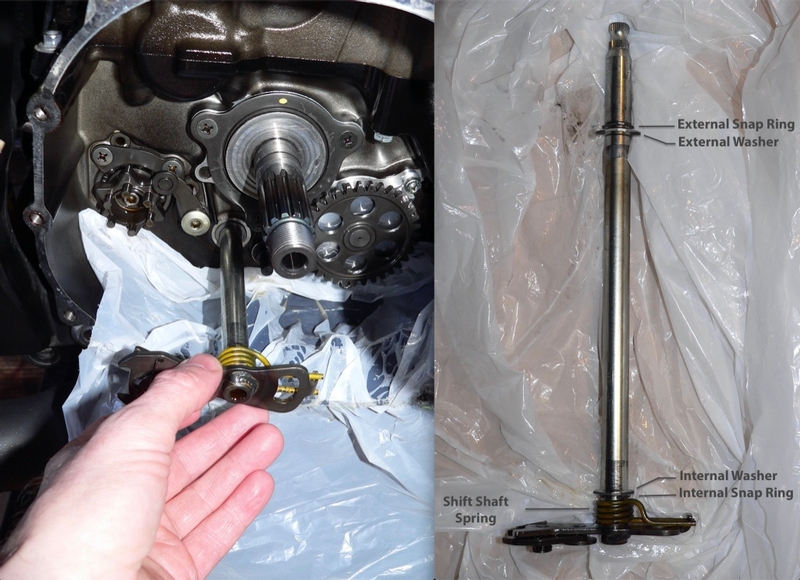
Be sure to remove the internal washer and mark which side faced out for reinstallation. There will also be an internal snap ring and a large painted wire spring on the shaft.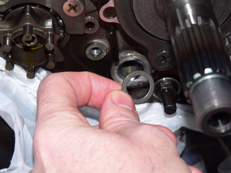
The internal washer might stick to the crankcase for a while. It will slide off eventually if you do not remove it.
6. Step 6 and steps 7 through 8 may be done in either order. I find it easier to leave the gear position lever in and remove the shift drum cam bolt first. Then lift the gear position lever with the flat of a screwdriver covered with a rag (photo, step 16) and pull out the shift drum cam.
Use a 5 mm hex tool bit to remove the gear positioning lever bolt.
Remove the gear positioning lever, collar and small spring wire.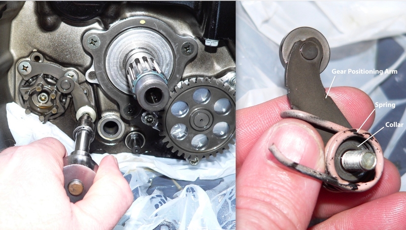
7. Use a 5 mm hex tool socket to remove the shift drum cam holder bolt.
The entire drum will turn to the 2nd gear position or perhaps even halfway into the 3rd gear position where it will lock in place. Continue to turn counterclockwise to break the bolt free and remove it.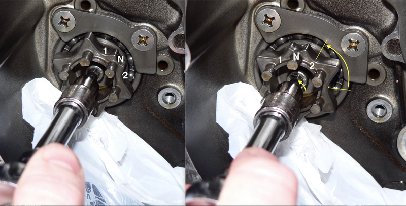
This is a tight one because there is thread locking agent on the bolt. Keep the bit square and pull. I was assured by a person well known throughout the ZX-14 racing community that no damage will come to any of the transmission parts that come after the drum cam. The other option is to remove the lower half of the crankcase, shift rods and forks, remove the phillips screws, pull the whole drum and place it in a vice to remove the cam bolt (see the Gen 1 service manual, p 9-44).
8. Remove the shift drum cam.
The dowel pin will probably remain lodged in place. If it is necessary to remove the dowel pin, mark it so it can be reinstalled in the same direction it was removed.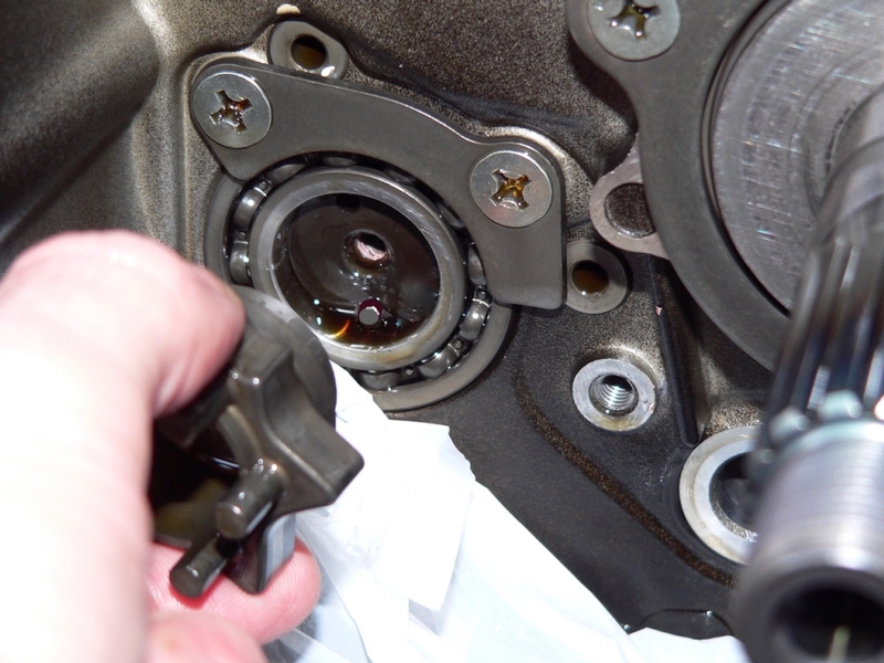
External Shift Mechanism Inspection
9. Visually examine the shift shaft assembly for damage.
Replace the shift pedal if it is bent or cracked.
Replace the shift pedal or shift shaft if either has damaged serrations.
If the shift shaft is bent, straighten or replace it.
Replace the shift shaft if either the inner or outer snap ring groove is worn or if there is any damage or wear to the gear shift mechanism arm.
If either the shift shaft return spring or the shift mechanism arm spring is damaged, replace it.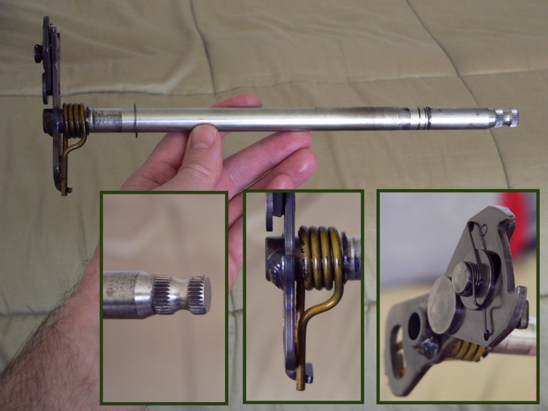
10. Check that the return spring pin is not loose and torque it if it is.
The service manual recommends the return spring pin to have non-permanent thread locking agent applied to its threads.
Torque - Shift Shaft Return Spring Pin: 29 N·m (3.0 kgf·m, 21 ft·lb) 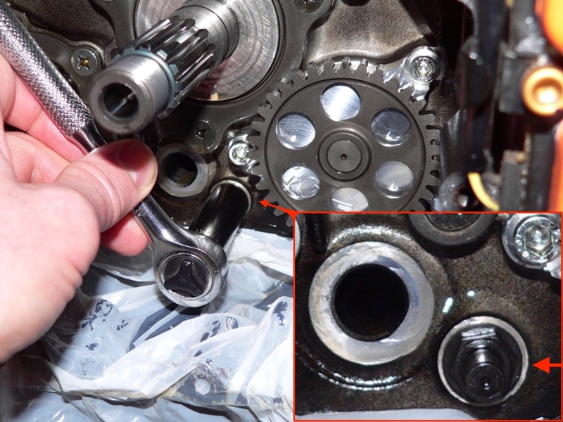
11. Replace the gear positioning lever and spring if they exhibit any cracks, distortion or bending.
Replace the shift drum cam if it is badly worn.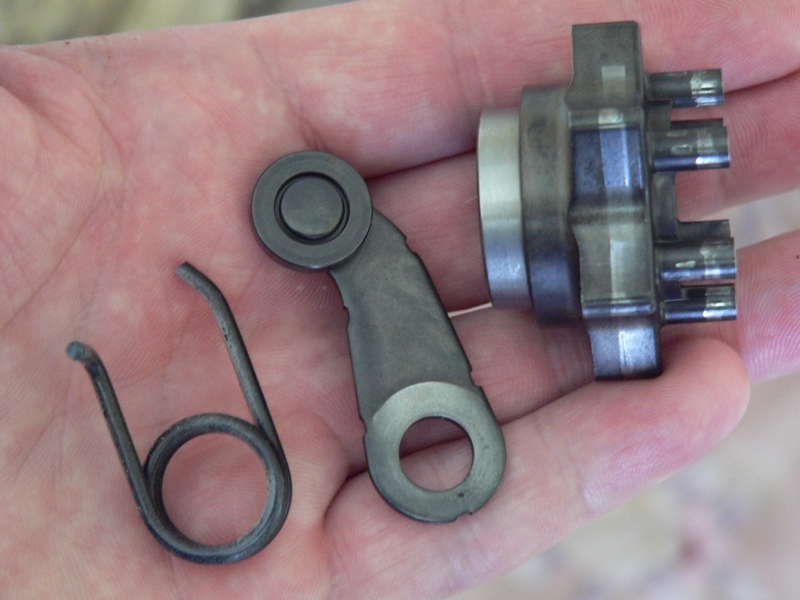
Installation
12. Wipe away every trace of loose thread locking agent present around the shift drum cam screw hole. Clean oil from the bolt hole threads of both the shift drum cam and the gear position lever. Insert a thin wood or plastic object covered with a rag soaked with mineral spirits. Turn the rag in a counterclockwise direction and repeat this procedure with a dry rag. Allow the threads to dry out thoroughly. 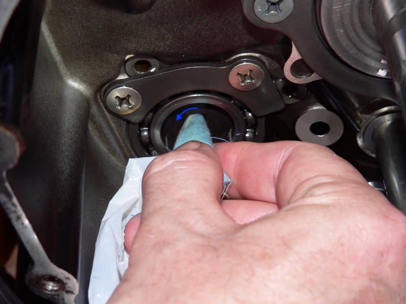
13. The service manual procedure is to install the shift star first and then squeeze the gear positioning arm into position. This can difficult to do properly with all the tension from the spring wire.
If you look closely at the picture below, you will see that the contour of the button head does not match the contour of the arm. The gear positioning lever is off center. The pivot hole has fallen between the collar and the bolt shoulder pinching the gear positioning lever rather than allowing it to pivot. If the bolt is torqued with the parts assembled this way, the gear positioning lever will be gouged and the bolt will bend. This situation can easily happen when installing either an OEM or Factory Pro gear positioning lever AFTER the shift drum cam has been installed. It is not so obvious when this problem is occurring because of the tension from the spring wire. The replacement parts cost an additional $115 including shipping.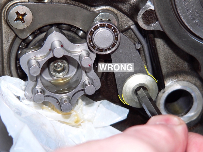
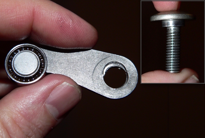
The gear positioning lever in the picture below has been installed before the shift drum cam. There is no tension in the spring and it is very easy to tell if there is a problem with the alignment of the gear positioning lever parts. Note the button head on the bolt and the edges of the gear positioning lever. The matching outer contours indicate that the parts are centered and properly assembled. Also, the gear positioning lever should swing loosely even as the parts are drawn together by the bolt. 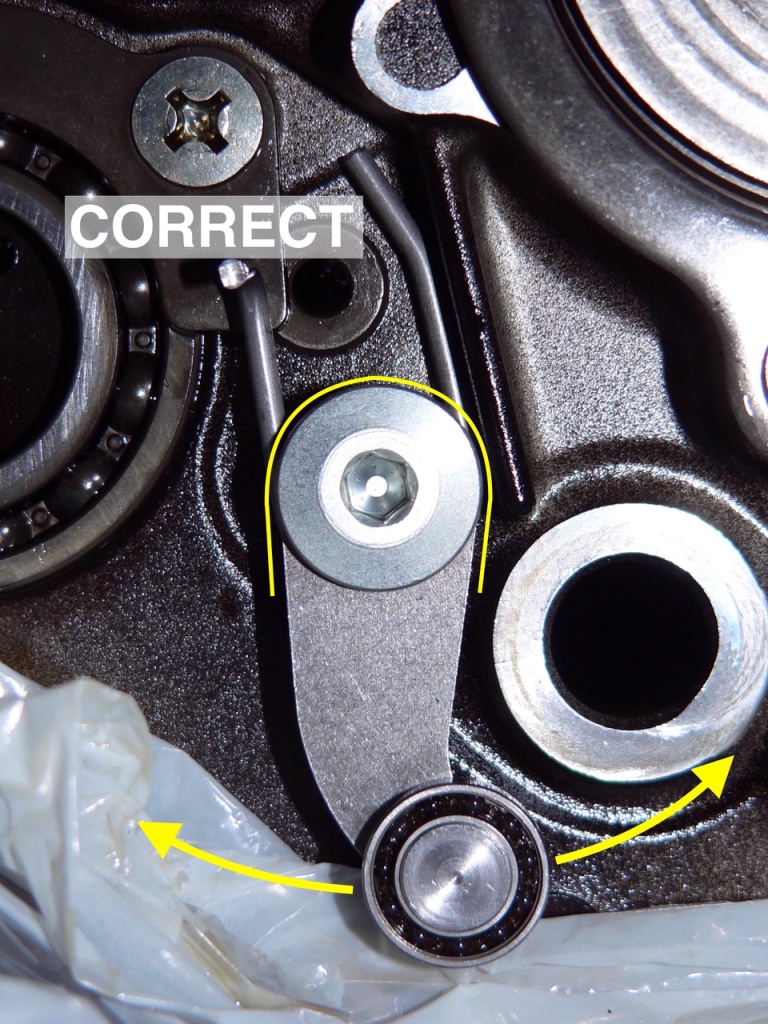
14. Assemble the bolt, gear positioning arm, collar and spring as shown in step 6. If you are installing a Factory Pro detent arm, reuse the OEM collar and bolt.
15. The service manual does not call for the use of thread locking agent on the gear positioning arm bolt. It cannot come out because it would hit the shift mechanism arm on the shift shaft but it could come loose and cause big problems. I think it would be wise to use a bit of LokTite 243 oil tolerant thread locking agent.
Thread the bolt in part way positioning the long portion of the spring against the ridge in the crankcase above the shift shaft tunnel. When the bolt is hand tight, its shoulder and the collar should form a continuous surface that the spring and arm can pivot on.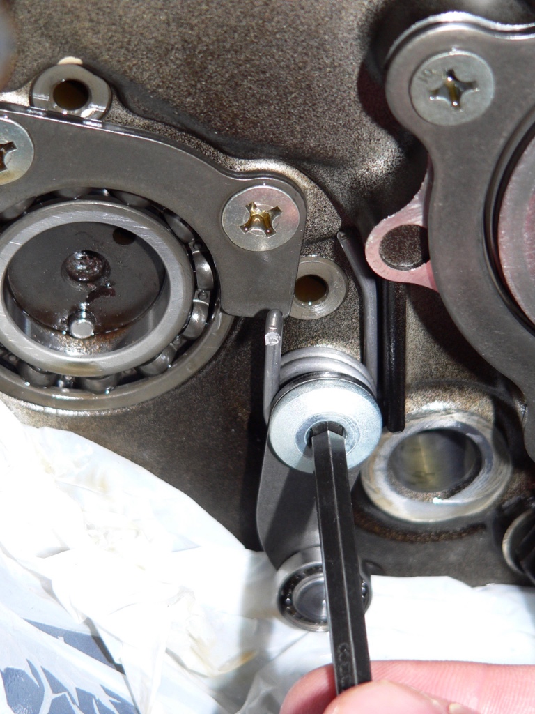
If the gear positioning arm does not pivot freely, it is off center and being pinched between the bolt shoulder and the collar. STOP! Loosen the bolt and position the gear positioning arm properly before drawing up the shoulder bolt and collar.
16. If it was removed from the shift drum, insert the dowel pin into the hole.
If the transmission is in N, installing the shift drum cam will be more difficult because the Neutral notch is higher than the gear notches (even more so with an EVO shift star). If the transmission turned halfway to third gear as you removed the shift drum cam bolt (step 7), this will also make installing the shift drum cam more difficult than if the transmission were to be put in 1 or 2.
Let the gear position lever hang downward and insert the shift drum cam to the shift drum, engaging the dowel pin. Turn the shift star by hand to first or second gear. If necessary, turn the input shaft in the clutch case or hold it still while turning the rear wheel to align the internal gear shifting mechanism. After shifting into gear, remove the shift star and resume the instructions below.
17. Note the orientation of the dowel pin hole in the back of the shift drum cam. Position the shift drum cam in your left hand so that it will mate with the dowel pin immediately upon inserting the shift drum cam to the shift drum.
With your right hand, compress the gear positioning lever spring by lifting the gear positioning lever using a straight slot screwdriver covered with a rag.
Position the gear positioning lever wheel into the gear notch on the shift drum cam that matches the gear position the transmission is in.
Use the shift drum cam to help push the detent arm forward along with the screwdriver while you pop the shift star into the shift drum. 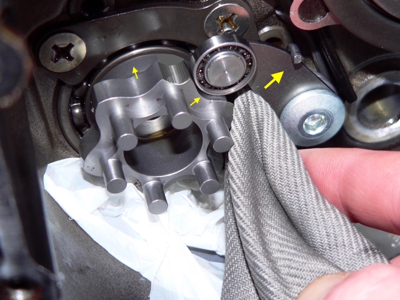
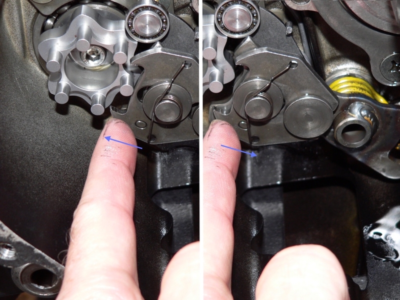
IMPORTANT—After the shift drum cam is in place, lift the gear position lever slightly and twist the shift star to verify that it is engaged to the dowel pin.
Do a close (and I mean CLOSE) visual inspection of the edge that adjoins the shift drum all around the shift drum cam. Feel this edge with your finger tips. If the edge is not perfectly even all around, the shift drum cam is not engaged to the dowel pin. Lift the gear position arm and twist the shift drum cam until it drops onto the dowel pin.
18. The service manual does call for nonpermanent locking agent on the shift drum cam holder bolt. Use medium strength LocTite 243 which is “oil tolerant,” slightly stronger and has a higher temperature rating than normal medium strength LocTite.
Insert the shift drum cam bolt through the shift cam and thread it into the shift drum cam. Verify that the shift drum cam is engaged to the dowel pin before tightening the bolt. The shift drum cam will probably shift to N or 1st gear as you tighten.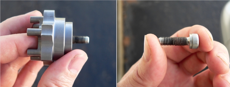
Even though any small, soft debris in the crankcase and clutch compartment will probably wash harmlessly to the oil pan where it will be trapped by the screen or filter, there is no sense in applying unneeded thread locking agent. Notice that the factory thread locking agent left on the bolt has clung to the length of threads inside the shift drum cam. I only applied LocTite 243 to the darkened portion of the bolt that exits the back of the shift drum cam. The female threads are about one quarter inch deep so no LocTite is needed at the tip of the threads.
19. With both the shift drum cam holder bolt and the gear position bolt tight, you should be able to safely test shift by placing both hands on the shift drum cam and turning between 1st and N. It may be necessary to align the internal shifting mechanism by turning the the input shaft and/or holding the input shaft while the rear wheel is turned.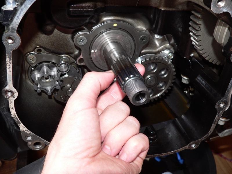
20. Use a torque wrench to tighten the shift drum cam holder bolt.
Torque - Shift Drum Cam Holder Bolt: 12 N·m (1.2 kgf·m, 106 in·lb)
Use non-permanent thread locking agent.
As the bolt is torqued, the shift drum may turn the transmission from second gear back to the Neutral position or it may continue to turn from Neutral to first gear where it will lock in place.
21. Use a torque wrench to tighten the gear positioning lever bolt.
Torque - Gear Positioning Lever Bolt: 12 N·m (1.2 kgf·m, 106 in·lb)
22. Be sure the internal washer and internal snap ring are on the shift shaft.
Squirt a bit of oil in the shift shaft tunnel from the clutchcase side and slide the shift shaft in. (reverse procedure of step 5). 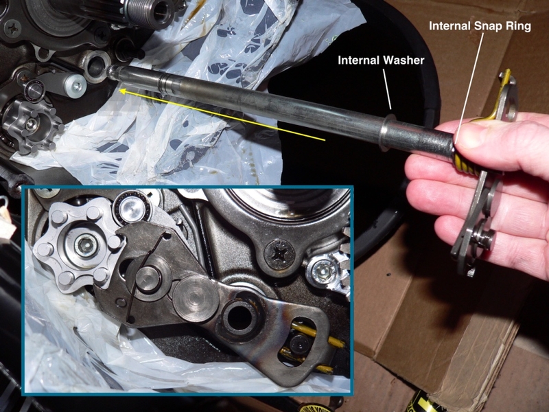
Engage the shift shaft return spring to its pin.
23. Lever the shift mechanism arm by hand to test shifts between 1st gear and Neutral.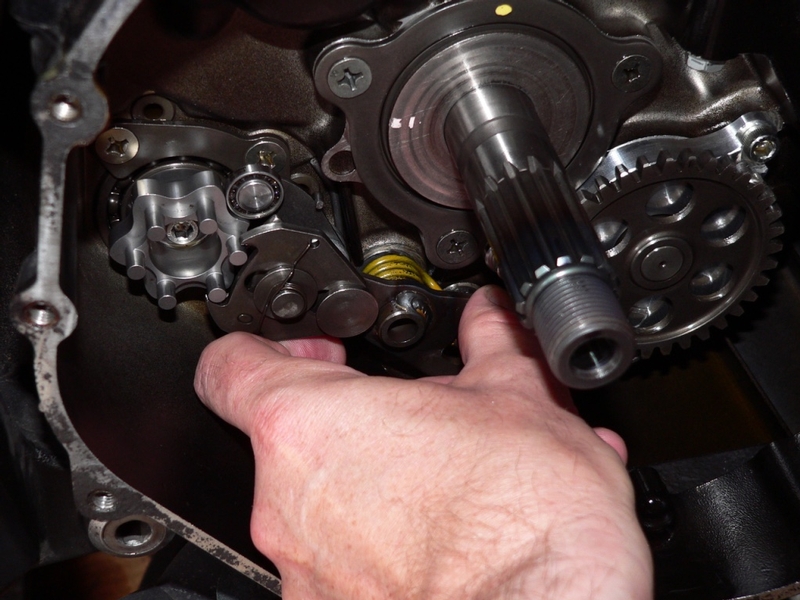
Don’t use pliers or vise-grips to turn the aluminum shift shaft. It will gouge even if you protect the surface with a rag and you probably won’t be able to get it out again without filing it.
If the claw of the shift mechanism arm retracts, that is ok. The small spring on the claw permits the clearance between it and the pins on the shift drum cam to vary.
24. Place the external washer over the serrated end of the shift shaft so the washer is positioned flat against the LH exterior of the crankcase. Be sure the needle bearing and oil seal are installed first.
Use a circlip pliers to install the external snap ring in its groove (reverse procedure of step 4).
Apply anti-seizing agent to the serrations of the shift shaft.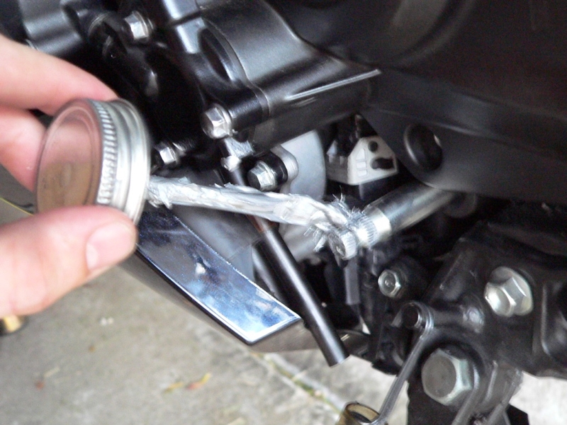
25. Be sure the shift pedal bolt is completely removed before installing the shift pedal to the shift shaft (see step 1).
Slide the shift pedal onto the shift shaft with the serrations aligned as they had been when removed (see steps 2 and 3).
26. Torque the shift pedal bolt. I suggest applying nonpermanent thread locking agent first because I have had this bolt fall out.
Torque - Shift Pedal Bolt: 6.9 N·m (0.70 kgf·m, 61 in·lb)
27. Test shifting from 1st gear to 2nd and from both 1st and 2nd to Neutral.
INSTALL CLUTCH HUB AND BASKET
INSTALL CLUTCH PLATES
INSTALL CLUTCH COVER
Weights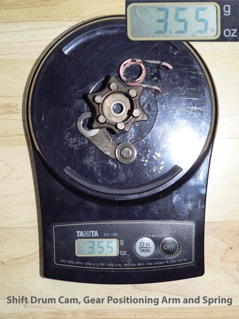
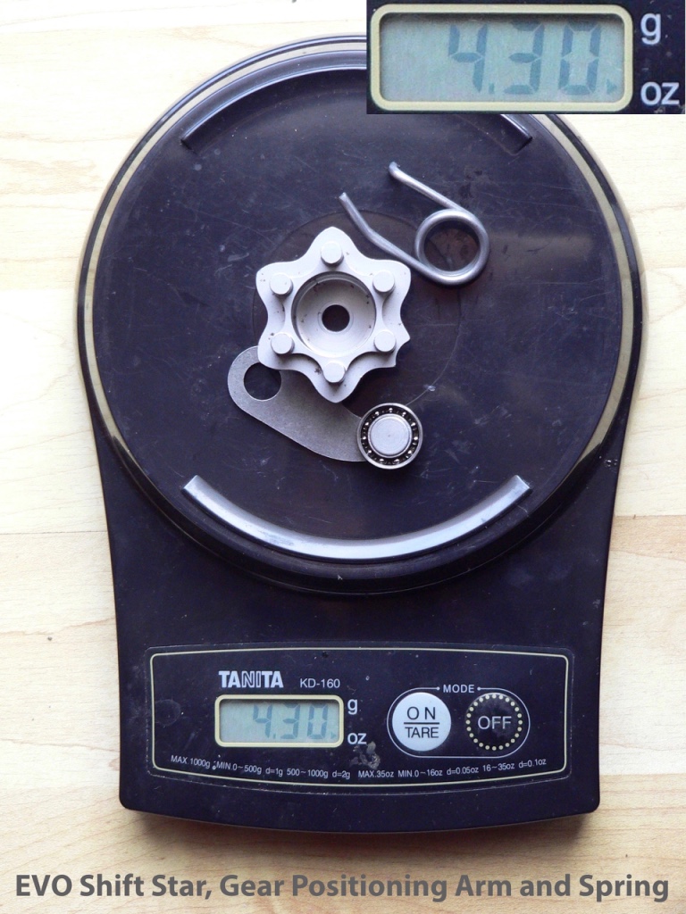
The EVO Shift Star mechanism weighs .75 oz more than OEM.